Multi-head linear motion mechanism for laser drilling
A linear motion, laser drilling technology, applied in laser welding equipment, welding/welding/cutting items, manufacturing tools, etc., can solve the problems of low module accuracy, reduced service life, equipment temperature effects, etc., to achieve simple structure, Ease of maintenance and reduction in quantity
- Summary
- Abstract
- Description
- Claims
- Application Information
AI Technical Summary
Problems solved by technology
Method used
Image

Examples
Embodiment Construction
[0026] Below in conjunction with specific embodiment and accompanying drawing, the present invention is further elaborated and illustrated:
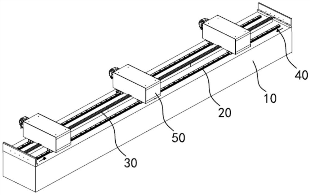
[0027] Please refer to figure 1 , a multi-head linear motion mechanism for laser drilling includes a base 10, a guide rail 20 located on the base 10, a rack 30, a plurality of first photoelectric induction switches 40, a plurality of mobile workbenches 50 and an electrical control device. The electrical control device is electrically connected to the first photoelectric sensor switch 40 and the mobile workbench 50 .
[0028] Please refer to figure 1 and Figure 4 , the rack 30 is fixed on the base 10 and is parallel to the guide rail 20 , a number of gear teeth are formed on the top surface of the rack 30 , and the bottom surface of the rack 30 is supported by the base 10 . Specifically, two guide rails 20 are arranged in parallel, and the rack 30 is located on the bisecting line between the two guide rails 20 . When the mobile workb...
PUM
 Abstract
Description
Claims
Application Information