A fixture for laser welding of fuel cell bipolar plates

A laser welding and fuel cell technology, applied in laser welding equipment, welding equipment, welding equipment, etc., can solve the problems of complicated welding process, achieve the effect of simplifying welding process and improving production tempo

Active Publication Date: 2022-04-26
DONGFENG MOTOR CORP HUBEI
View PDF0 Cites 1 Cited by
  • Summary
  • Abstract
  • Description
  • Claims
  • Application Information

AI Technical Summary

Problems solved by technology

[0005] In view of this, the purpose of the present invention is to overcome the deficiencies of the prior art and provide a fixture for laser welding of fuel cell bipolar plates to solve the technical problem of complex welding processes in the prior art

Method used


Image

  • A fixture for laser welding of fuel cell bipolar plates
  • A fixture for laser welding of fuel cell bipolar plates
  • A fixture for laser welding of fuel cell bipolar plates

Examples


Embodiment 1

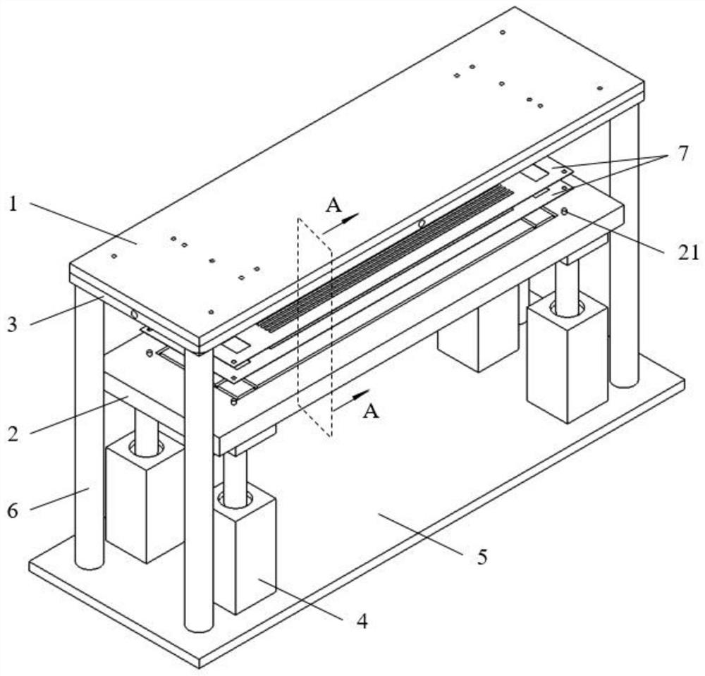
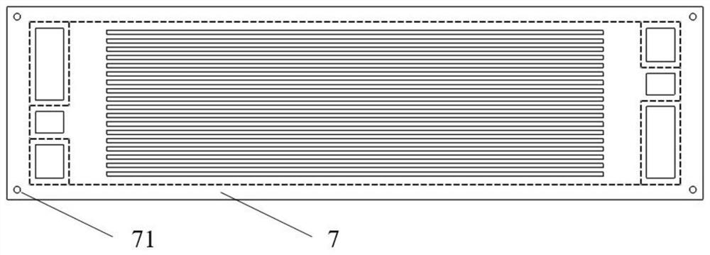
[0036] Such as figure 1 As shown, a fixture for laser welding of a fuel cell bipolar plate 7 includes a first press plate 1, a second press plate 2, a profiling plate 3, a driving device 4, a bottom plate 5 and a support member 6, wherein,

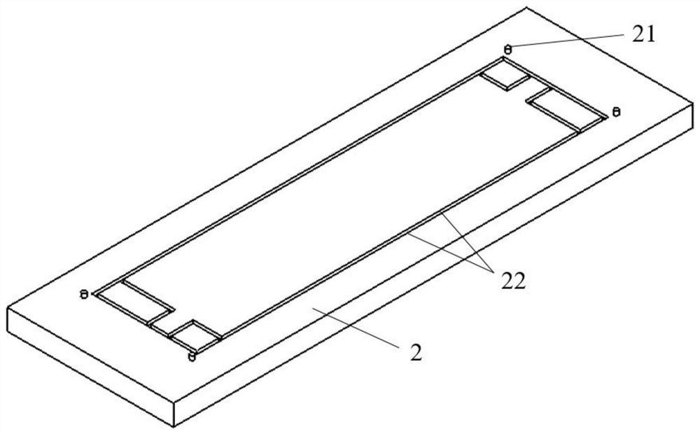
[0037] Both the first pressing plate 1 and the second pressing plate 2 are straight plates. The first platen 1 is made of materials capable of penetrating laser light 8 , such as transparent quartz glass, transparent sapphire glass and the like. The second pressing plate 2 , the profiling plate 3 , the bottom plate 5 and the supporting member 6 are made of metal parts such as steel or aluminum alloy. The first pressing plate 1 is horizontally fixed on the bottom plate 5 through the support member 6, the second pressing plate 2 is fixed horizontally on the bottom plate 5 through the driving device 4, and the first pressing plate 1 is located directly above the second pressing plate 2 and the first pressing plate 1 It is spaced apart from ...

Embodiment 2

[0055] This embodiment is another embodiment of Embodiment 1. In this embodiment, the material of the profiling plate 3 is made of a material through which the laser light 8 can pass, such as transparent quartz glass or transparent sapphire glass. The rest of the structure of this embodiment is the same as that of Embodiment 1.

[0056] Such as Figure 9 As shown, when long-distance galvanometer laser welding is used, the angle between the path of the laser 8 and the bipolar plate 7 is small, and the laser 8 must pass through the profiling plate 3 to be irradiated on the surface of the bipolar plate 7 Therefore, after the material of the profiling plate 3 is set to a material through which the laser 8 can pass, long-distance galvanometer laser welding can be realized to ensure the welding quality in the long-distance area. When the format of the bipolar plate 7 is large, there is no need to move the emitting end of the laser 8 to a large extent, only need to adjust the emitti...


PUM


Abstract

The invention relates to a fixture for laser welding of fuel cell bipolar plates, which belongs to the technical field of fuel cells. The fixture includes a first pressing plate, a second pressing plate, a profiling plate and a driving device, wherein the first pressing plate can transmit laser light; the second pressing plate is spaced apart from the first pressing plate, and the second pressing plate is used for To fix the bipolar plate; the profiling plate is fixed on the side of the first pressure plate close to the second pressure plate, and the profiling plate is provided with a laser avoidance groove for the laser to pass through and a smoke channel connected with the laser avoidance groove; the driving device drives the second pressure plate The first pressing plate and / or the second pressing plate move towards each other and clamp and fix the bipolar plate. After the bipolar plate is fixed by the clamp, the laser beam of the laser welding equipment can penetrate the first pressing plate and the laser avoidance groove to reach the bipolar plate, realizing one-time clamping and welding of the bipolar plate. At the same time, the smoke generated by welding is discharged from the laser avoidance groove through the smoke channel to prevent the smoke from affecting the penetration of the laser and affecting the welding effect of the laser.

Description

technical field [0001] The invention belongs to the technical field of fuel cells, in particular to a fixture for laser welding of fuel cell bipolar plates. Background technique [0002] The bipolar plate is an important part of the hydrogen fuel cell, which plays the role of gas distribution, water and heat management, current collection, and support for the stack. At present, the commonly used material for bipolar plates is 316L stainless steel, with a thickness of 0.07-0.1mm. Usually, the raw materials are stamped into cathode plates and anode plates with fine flow channels, and then the two unipolar plates are connected together to form a "two plates". Three Fields" structure. Compared with other connection technologies, laser welding has the advantages of simple process, fast speed, good sealing, high joint quality, and easy automation. It is a commonly used connection process in the mass production of metal bipolar plates. [0003] In order to effectively isolate the...

Claims


Application Information

Patent Timeline
Patent Type & Authority Patents(China)
IPC IPC(8): B23K37/04B23K26/70B23K26/21B23K26/142
CPCB23K37/0435B23K26/702B23K26/21B23K26/142
Inventor 王慧张新丰王手龙
Owner DONGFENG MOTOR CORP HUBEI
Why Eureka
Try Eureka