Mechanical burnishing equipment

A mechanical grinding and equipment technology, which is applied in grinding/polishing equipment, metal processing equipment, grinding machines, etc., can solve problems such as inability to perform grinding or precise processing, low work efficiency, and affect the quality of grinding, so as to improve work efficiency and use performance, avoiding rust or sparks, and avoiding accidental injury to workers

Active Publication Date: 2021-03-26
南京宁宣机械制造有限公司
View PDF7 Cites 1 Cited by
  • Summary
  • Abstract
  • Description
  • Claims
  • Application Information

AI Technical Summary

Problems solved by technology

[0005] In order to solve the technical problems existing in the background technology, the present invention proposes a mechanical grinding equipment, which solves the problem that the existing grinding equipment for plate parts is too simple in structure, inconvenient to use, and some plate surfaces are seriously corroded and delaminated. , during the grinding process, rust slag will accumulate, and then rust slag will rub on the surface of the plate, causing friction marks on the polished surface, making the grinding effect poor, seriously affecting the quality of grinding, and the function is single, it can only be used on the surface Simple processing, unable to perform grinding or precise processing, it is necessary to move the plate to different equipment for processing, which is time-consuming and laborious, and the work efficiency is low. Traditional equipment has great limitations, which reduces the problem of performance

Method used


Image

  • Mechanical burnishing equipment
  • Mechanical burnishing equipment
  • Mechanical burnishing equipment

Examples


Embodiment Construction

[0036] In order to make the object, technical solution and advantages of the present invention clearer, the present invention will be further described in detail below in combination with specific embodiments and with reference to the accompanying drawings. It should be understood that these descriptions are exemplary only, and are not intended to limit the scope of the present invention. Also, in the following description, descriptions of well-known structures and techniques are omitted to avoid unnecessarily obscuring the concept of the present invention.

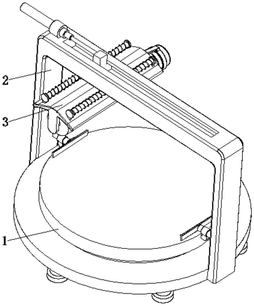
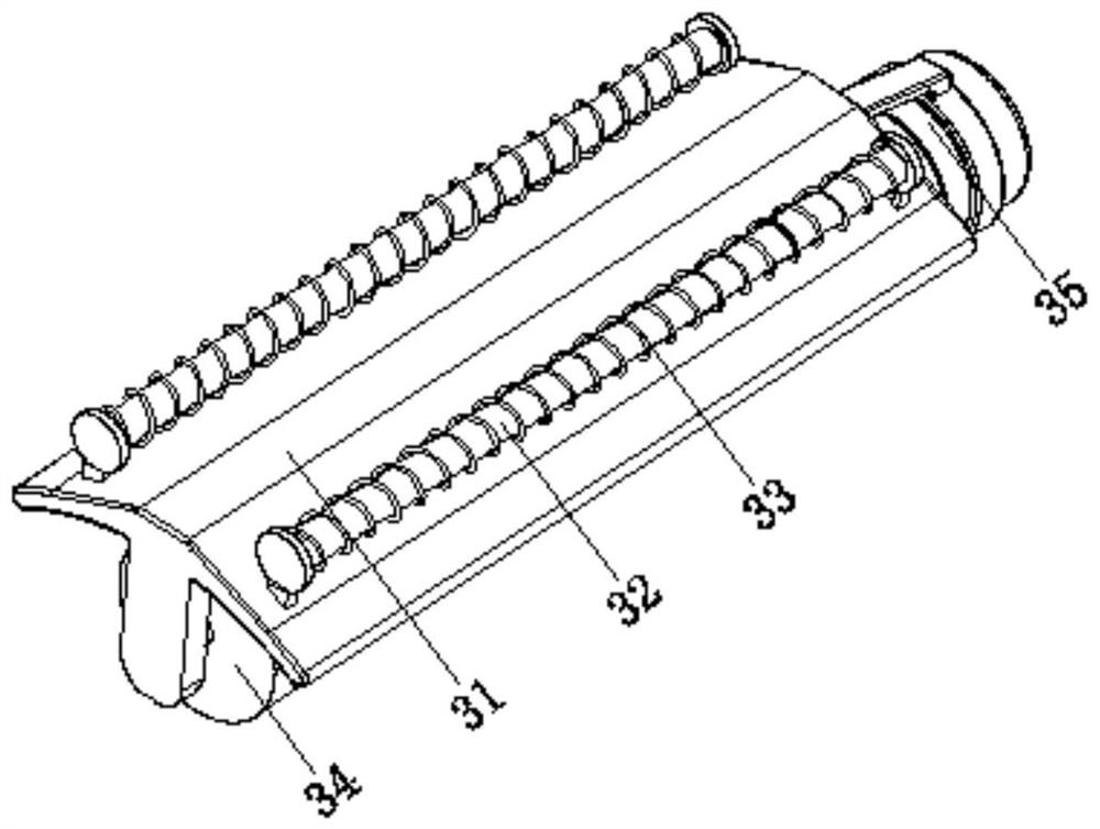
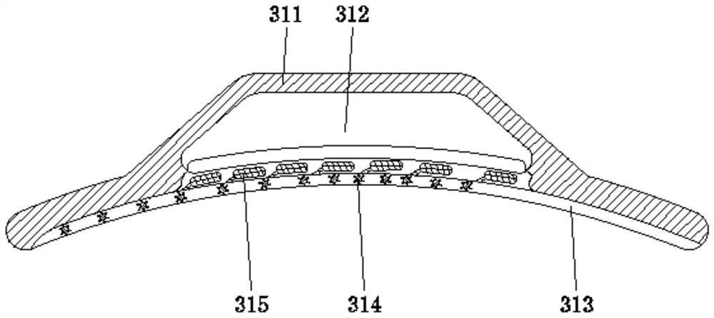
[0037] Such as Figure 1-8 As shown, a kind of mechanical grinding equipment proposed by the present invention includes a lift body 1, a support linear transmission mechanism 2, and a surface treatment device 3. The support linear transmission mechanism 2 is fixed at the center of the top surface of the lift body 1, and the surface treatment device 3 is arranged on Inside the support linear transmission mechanism 2 and a...


PUM


Abstract

The invention discloses mechanical burnishing equipment. The mechanical burnishing equipment comprises a lifting machine body, a bracket linear transmission mechanism and a surface treatment device, wherein the bracket linear transmission mechanism is fixed to the center of the top of the surface of the lifting machine body, and the surface treatment device is arranged in the bracket linear transmission mechanism and located above the lifting machine body. Iron rods are fixed to the two corresponding sides of the top of a housing deslagging device, a coil is arranged on the surface of each ofthe iron rods, a burnishing device is arranged at the bottom of the housing deslagging device through a bracket, and a driving motor is fixed to the end of the housing deslagging device through a machine frame. The invention relates to the technical field of burnishing equipment. The mechanical burnishing equipment achieves the effect of being high in adaptability, rust slag can be collected, thesituation that the surface burnishing quality is affected due to accumulation of the rust slag is avoided, besides, grinding can be performed, grinding, burnishing and dust removing are integrated, equipment does not need to be replaced frequently, limitation is reduced, and the working efficiency and the using performance are improved.

Description

technical field [0001] The invention relates to the technical field of grinding equipment, in particular to a mechanical grinding equipment. Background technique [0002] In the coating, the surface of the object to be coated or the coating film is rubbed with friction media such as sandpaper, pumice, and fine stone powder, which is called grinding. It is an important step in the painting process. It is usually done manually, but it can also be done with pneumatic or electric equipment. Grinding runs through the entire painting process, not only for blanks, primers or putty, but also after topcoating. Its function is to remove burrs, floating rust, oil stains and dust on the surface of the substrate; remove coarse particles and impurities on the surface of the coating to obtain a smooth surface; polish the smooth coating surface to a certain roughness to enhance the adhesion of the coating. Focus on. Divided into dry sanding and wet sanding, the latter is lubricated with ...

Claims


Application Information

Patent Timeline
Patent Type & Authority Applications(China)
IPC IPC(8): B24B7/10B24B27/033B24B55/06B24B55/12
CPCB24B27/033B24B7/10B24B55/06B24B55/12Y02P70/10
Inventor 李宣红
Owner 南京宁宣机械制造有限公司
Why Eureka
Try Eureka