
Industrial polishing brush for plate processing

A plate processing and polishing brush technology, applied in metal processing equipment, surface polishing machine tools, grinding/polishing equipment, etc., can solve the problems of uneven polishing of metal plate surface, reduced practicability, and reduced polishing effect of metal plate surface , to achieve the effect of improving the polishing effect, extending the service life, improving the effect and efficiency

Inactive Publication Date: 2021-03-26
安徽省潜山县天柱刷业有限公司
View PDF8 Cites 0 Cited by
  • Summary
  • Abstract
  • Description
  • Claims
  • Application Information

AI Technical Summary

Problems solved by technology

[0004] The purpose of the present invention is to provide an industrial polishing brush for plate processing, to solve the problem that the disk-shaped polishing brush plate and the brush wire are fixed in the prior art, and when the surface of the plate metal is polished, the plate There are some bumps on the surface of the polishing brush, so that the brush wire at the bottom of the polishing brush is in conflict with the surface of the plate. The polishing brush rotates at a high speed to perform polishing work. Because the force exerted by the brush plate on the brush wire is uniform, resulting in uneven polishing of the metal plate surface , greatly reducing the polishing effect on the metal plate surface, and it is not convenient to quickly clean up the waste generated by polishing, which will affect the polishing operation of the plate surface, resulting in a problem that the practicability is greatly reduced

Method used


Image

  • Industrial polishing brush for plate processing
  • Industrial polishing brush for plate processing
  • Industrial polishing brush for plate processing

Examples


Embodiment

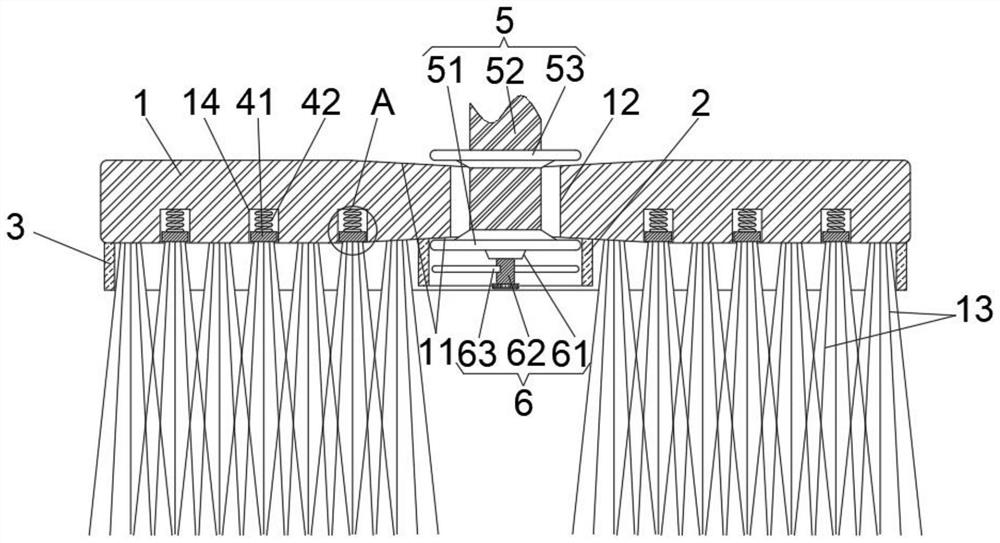
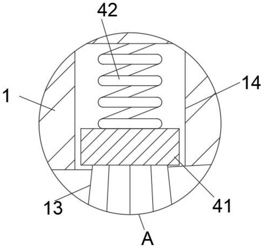
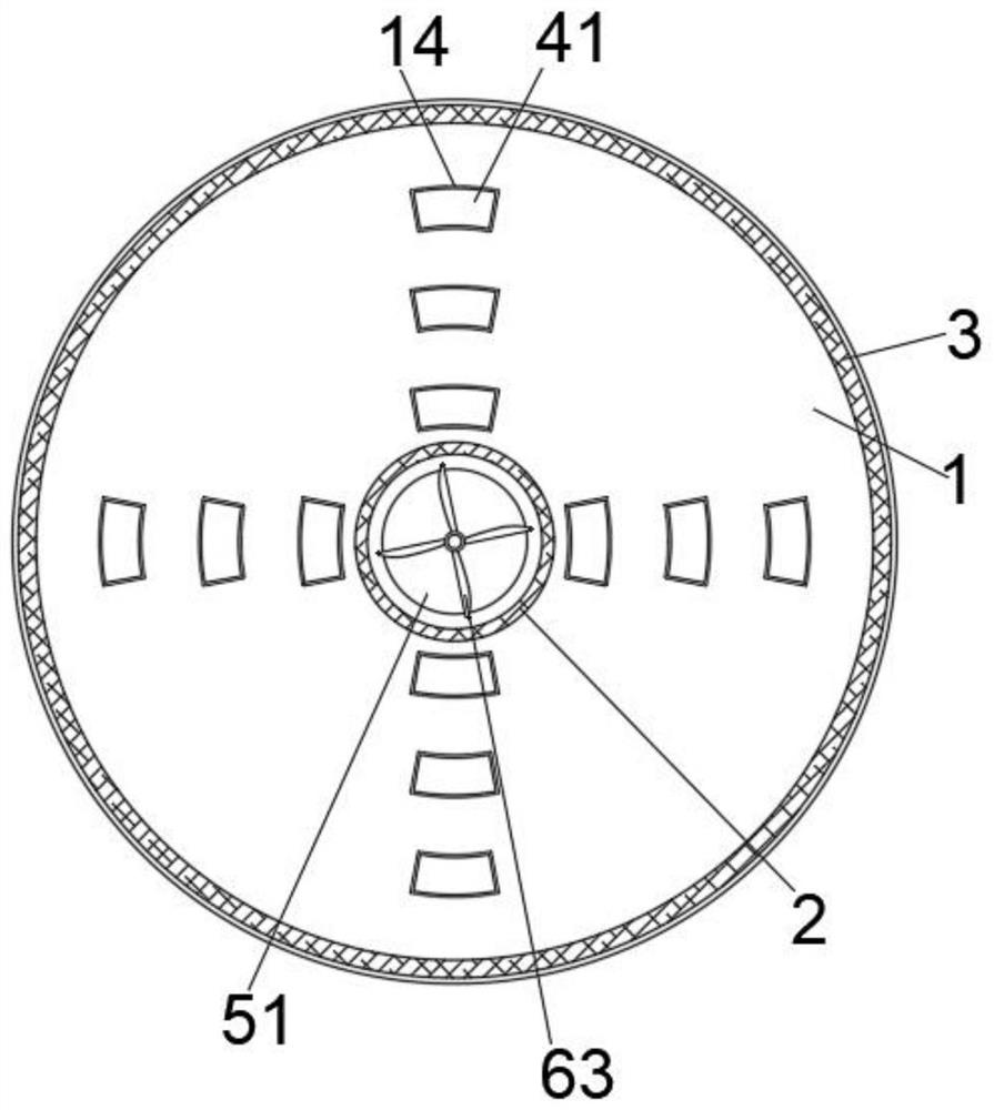
[0021] see Figure 1-3 As shown, the present invention provides a technical solution for industrial polishing brushes for plate processing: including the brush plate 1 and the adapter groove 14 provided on the ground of the brush plate 1, the adapter groove 14 is evenly distributed in a circumferential shape, and the adapter groove 14 is equipped with There is an adjustment component, which makes the polishing brush more suitable for the polishing operation of the metal plate surface with bumps. The middle part of the brush plate 1 is provided with a mounting mechanism 5, and the mounting mechanism is used for fast and stable assembly of the polishing brush. The bottom of the mechanism 5 is provided with a dust removal mechanism 6, which is used to effectively blow off the dust generated in the polishing operation, thereby further improving the polishing effect;

[0022] The adjustment assembly includes an adjustment block 41, the adjustment block 41 is slidably connected with...


PUM


Abstract

The invention relates to the technical field of industrial brushes, and discloses an industrial polishing brush for plate processing. The industrial polishing brush comprises a brush plate and adaptive grooves formed in the ground of the brush plate; the adaptive grooves are uniformly distributed in a circumferential shape, and adjusting assemblies are arranged in the adaptive grooves; a mountingmechanism is arranged in the middle of the brush plate, the brush plate rotates at a high speed to drive brush wires to polish a metal plate surface, so that when the brush wires located at the bottomof an adjusting block abut against a protruding block part, an adaptive spring is driven to contract due to the action of extrusion force, namely the adjusting block is driven to move upwards till the brush wires located at the bottom of the adjusting block are attached to the protruding block, and the brush plate rotates at a high speed to polish the metal plate surface; and after polishing of the protruding block part is completed, the adaptive spring releases elastic acting force along with reduction of the protruding block, the adjusting block is slowly driven to move downwards till polishing of the protruding block is completed, namely, the brush wires located at the bottom of the adjusting block are flush with the brush wires located at the bottom of the brush plate, more uniform polishing operation is conducted, and the polishing effect on the metal plate surface is improved.

Description

technical field [0001] The invention relates to the technical field of industrial brushes, in particular to an industrial polishing brush for plate processing. Background technique [0002] Industrial brushes are new types of products that are upgraded and improved on the basis of civilian brushes. They are mainly used for cleaning, dust removal, polishing, etc. in the industrial production process. At this stage, polishing brushes are a very widely used brush product. It is mainly used to deburr and finely polish the surface of the thrown object. It is mainly made of iron wire (steel wire) as the skeleton, with many fine brush wires arranged neatly on it and stretched outward. The brush wire material is nylon. Silk, fiber hair, bristle, steel wire, copper wire, abrasive wire, etc., have different scopes of use. [0003] At present, when using industrial polishing brushes, especially the use of disc-shaped polishing brushes, the existing disc-shaped polishing brush plates a...

Claims


Application Information

Patent Timeline
Patent Type & Authority Applications(China)
IPC IPC(8): B24B29/00B24B41/04B24B55/06
CPCB24B29/005B24B41/04B24B55/06
Inventor 雷丁苗曹虹梅
Owner 安徽省潜山县天柱刷业有限公司
Learn More