Electromagnetic-heating silicon rubber roller and processing method thereof

A processing method and technology of silicone rollers, applied in printing, printing presses, rotary printing presses, etc., can solve the problems of reduced transfer efficiency, adhesive failure, limited contact area, etc., to improve the thermal transfer rate, reduce The loss of energy, the effect of breaking the transfer difficulty

Active Publication Date: 2021-03-26
四川峻发鑫材环保设备有限公司
18 Cites 0 Cited by

AI-Extracted Technical Summary

Problems solved by technology

[0004] 1. The contact heating area of ​​the external heating silicone roller and the external heating device is limited, generally at most 1/3 of the outer circumference of the silicone roller, which requires extremely high power of the heating device, at least 15KW or more , higher heating costs;
[0005] 2. When preheating the silicone roller, it is necessary to keep the silicone roller rotating to heat the whole roller, which requires adding a separate transmission device to the silicone roller, which further increases the use cost of the silicone roller. At the same time, the volume of the silicone roller is increased, which increases the difficulty of installation;
[0006] 3. During thermal transfer printing, it is generally necessary to heat the silicone roller until the surface temperature reaches 160-200°C. However, due to the limited contact area between the silicone roller and the heating device, if you want to heat the silicone roller until the surface temperature reaches 180°C , it needs to be heated for at least 2 hours, which makes the preheating time for each startup long and reduces the work efficiency;
[0007] 4. Since a part of the silicone roller needs to be separated to contact with the heating device, the contact area between the thermal transfer film and the silicone roller is greatly compressed, leaving only 1/4 of the outer circumference of the silicone ro...

Abstract

The invention discloses an electromagnetic-heating silicon rubber roller and a processing method thereof. The electromagnetic-heating silicon rubber roller comprises a coil bracket, an electromagneticline and a silicon rubber roller, wherein the coil bracket is made of a non-magnetic material; the electromagnetic line is wound on the coil bracket, and is connected to a high-frequency power supply; the silicon rubber roller sleeves outside the coil bracket; the silicon rubber roller comprises a metal roller inside and a silicon rubber layer coated outside the metal roller; the thickness of thesilicon rubber layer is smaller than or equal to 4 mm; and the electrometric line is heated up for heating the silicon rubber roller. The electromagnetic-heating silicon rubber roller provided by theinvention overcomes the defects of the silicon rubber roller in the prior art, so that the outer surface temperature of the silicon rubber roller can be 300 DEG C or higher; and moreover, the electromagnetic-heating silicon rubber roller can be stably used for a long term, so that the use range of the electromagnetic-heating silicon rubber roller is effectively expanded.

Application Domain

Technology Topic

Image

  • Electromagnetic-heating silicon rubber roller and processing method thereof
  • Electromagnetic-heating silicon rubber roller and processing method thereof
  • Electromagnetic-heating silicon rubber roller and processing method thereof

Examples

  • Experimental program(1)

Example Embodiment

[0059] Example 1
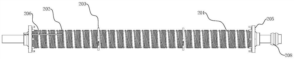
[0060] Please refer to Figure 2-4 As shown, this embodiment provides an electromagnetically heated silicone roller, which includes: a coil bracket 201, which is made of non-magnetic material, such as a ceramic bracket or a refractory cement bracket, and in order to reduce weight and facilitate installation, the coil bracket The frame 201 can be a hollow cylinder, and at the same time, 2-3 non-magnetic threaded steel rods with a diameter of 6-8mm can be arranged in the coil bracket 201 to enhance the strength of the coil bracket and make the coil bracket more durable; Electromagnetic wire 202, which can withstand high temperature, is wound on the coil bracket 201, and the electromagnetic wire 202 is connected with a high-frequency power supply to supply heat for the electromagnetic wire 202, so as to realize the effect of electromagnetic induction heating; the silicone roller is set on the coil bracket Outside the frame 201, the silicone roller includes a metal roller 207 inside and a silicone layer 204 coated outside the metal roller 207. The thickness of the silicone layer 204 is ≤ 4mm. The electromagnetic wire 202 is energized and heated to heat the silicone roller.
[0061] See figure 1 As shown, the traditional externally heated silicone roller is usually heated by electromagnetic coil induction heating, but it needs to set a separate external heating device and a separate transmission mechanism outside the silicone roller to drive the silicone roller during preheating. Rotate to heat the silicone roller evenly. When heating, the effective contact area between the silicone roller and the heating device is generally only 1/3 at most. For example, if the surface temperature is 180°C, it needs to rotate for at least 2 hours. This still requires the power of the heating device to be maintained at least 15kw, which makes the preheating of the silicone roller consume a lot of energy. However, the electromagnetically heated silicone roller 1 in this embodiment is internally heated as a whole, and does not need to be provided with a separate heating device outside, and the contact area reaches 100%. At the same time, during preheating, the electromagnetically heated silicone roller 1 is not required Rotation, relatively speaking, not only simplifies the structure, but also shortens the warm-up time, greatly reduces energy consumption, and helps reduce the production cost of the enterprise.
[0062] At the same time, when applied to the heat transfer printing industry, the traditional externally heated silicone roller needs to reserve about 1/3 of the outer circumference of the silicone roller for heating, otherwise it is easy to make the heat of the silicone roller insufficient and heat transfer The heat of the printing film is poor, which affects the effect of thermal transfer printing, which causes the contact area between the silicone roller and the thermal transfer film to be at most 1/4 of the outer circumference of the silicone roller, and the transfer speed cannot be too fast. And the electromagnetically heated silicone roller 1 in this embodiment, in the thermal transfer process, because the electromagnetically heated silicone roller 1 is internally heated, it does not need to reserve a heating part outside, so that the thermal transfer film and the electromagnetically heated silicone roller The contact area of ​​1 can reach 2/3 of the outer circumference of the electromagnetic heating silicone roller 1. Compared with the traditional external heating silicone roller, the contact area between the thermal transfer film and the silicone roller is greatly increased, and the The heating rate of the thermal transfer film makes the thermal transfer speed can be greatly accelerated, thus effectively improving the production efficiency of the enterprise.
[0063] Wherein, in order to facilitate the installation of the metal roller 207 and the coil bracket 201, the coil bracket 201 is detachably provided with at least one support ring 203, the support ring 203 can be a tetrafluoro support ring 203, and at the same time, the support ring 203 can be It is a ring shape with an opening and is fixed by bolts at the opening. The magnet wire 202 is wound on the coil bracket 201 , and the metal roller 207 is against the outside of the support ring 203 so as not to squeeze the magnet wire 202 . When assembling, the silicone layer 204 is coated on the metal roller 207, and the electromagnetic wire 202 is wound on the coil bracket 201, and then the coil bracket 201 is fixed, and then the coil bracket 201 is sent into the metal roller 207, then utilize the connection flange 205 to connect the two, and connect the motor that provides kinetic energy on the connection flange 205 to drive the electromagnetic heating silicone roller 1 to rotate for thermal transfer printing, and for the electromagnetic wire 202 and the high-frequency power supply A through hole for the thermocouple 206 to pass through can be set on the connecting flange 205 at one end, and a high-power conductive ring 208 can be set on the connecting flange 205 at the other end.
[0064] Among them, the reason why the existing internal heating silicone roller cannot be used in the thermal transfer printing industry is that the thickness of the silicone layer 204 is too thick, resulting in a large temperature difference between the inside and the outside, which cannot meet the temperature requirements of thermal transfer printing. In order to overcome this problem, this The embodiment provides a new processing method, which specifically includes the following steps:
[0065] (1) Apply an adhesive on the surface of the metal roller 207, and use a rubber encapsulation machine to evenly distribute the silica gel on the surface of the metal roller 207 to form a seamless adhesive layer;
[0066] (2) The metal roller 207 is sent into a vulcanizing machine for vulcanization to obtain a silica gel roller;
[0067] (3) Wind the electromagnetic wire 202 on the coil bracket 201 , and then put the silicone roller on the outside of the coil bracket 201 .
[0068] Adhesives are also called adhesives, which can be selected from imported adhesives resistant to high temperatures of 260°C, and the glue used as the silica gel layer 204 can include the following components by weight: nano-aluminum nitride powder 3%-5%, Vulcanizing agent 0.5%-1.5%, raw silica gel 90%-96%; use nano-aluminum nitride powder to modify raw silica gel to improve its thermal conductivity and further reduce the temperature difference between the inside and outside of the silica gel roller.
[0069] The electromagnetic heating silica gel roller 1 prepared by the above method, when heating and heating, the electromagnetic heating silica gel roller 1 is energized by the electromagnetic wire 202 to heat the electromagnetic heating silica gel roller 1 as a whole, and the silica gel layer modified with nano-scale aluminum nitride powder and 2 mm thick Take 204 as an example, the heating power is 5kw, from the surface temperature of the silica gel layer 204 is 20 ℃ to the surface temperature of the silica gel layer 204 is 180 ℃, it generally only takes 40 minutes, and the temperature of the metal roller 207 will not exceed 230 ℃ at this time , will not affect the combination between the silica gel layer 204 and the metal roller 207, so that the electromagnetically heated silica gel roller 1 can adapt to the temperature requirements in the thermal transfer process, and can realize the rapid temperature rise of the electromagnetically heated silica gel roller 1, greatly The warm-up time of the electromagnetically heated silicone roller 1 is reduced to reduce energy loss.
[0070] For lagging machines with improved processing methods, see Figure 5-8 As shown, it includes a first cover roller 8; a second cover roller 9, which is arranged in parallel with the first cover roller 8; a mounting flange 1002, which is located between the first cover roller 8 and the second cover roller 9 Between them, there are two mounting flanges 1002 symmetrically arranged, and the metal roller 207 is installed on the mounting flange 1002, and the metal roller 207 is parallel to the first rubber roller 8; the adjusting device drives the first rubber roller 8 The thickness of the silica gel layer 204 is adjusted by approaching or moving away from the second rubber covering roller 9; the first driving device drives the first rubber covering roller 8 and the second rubber covering roller 9 to rotate for rubber covering. To put it simply, the rubber is extruded and coated on the outside of the metal roller 207 through the first rubber-covering roller 8 and the second rubber-covering roller 9 to realize the rubber-covering, and the thickness of the rubber-covering is mainly controlled by the adjusting device.
[0071]Among them, the first rubber-coated roller 8 is the main rolling roller. When rubber-coating, the raw material glue is put between the first rubber-coated roller 8 and the metal roller 207, and the glue is pressed on the metal roller 207 by the first rubber-coated roller 8. On the roller 207, the metal roller 207 will rotate together with the first rubberized roller 8 and the second rubberized roller 9 under the effect of friction, and the place where the glue is glued will be rotated to match the second rubberized roller. 9 contact side to squeeze, so that the thickness of the silica gel layer 204 meets the requirements, so the distance between the first rubber-covered roller 8 and the metal roller 207 needs to be slightly larger than the distance between the second rubber-covered roller 9 and the metal roller 207 distance, which requires the adjustment device to adjust the positions of the first rubber-coated roller 8 and the second rubber-coated roller 9 respectively. For this, the rubber-coated machine also includes a frame 7 and a wallboard fixedly installed on the top of the frame 7 10. There are two wallboards 10, which are divided into two ends located at the two ends of the frame 7. In order to make the fixing effect of the wallboard 10 better and increase the stability of the wallboard 10, a brace can be set between the two wallboards 10. Tie rod 1003, the two ends of the support rod 1003 are fixedly connected with two wall panels 10 respectively, and the number of support rods 1003 can be set to one or more, as long as the wall panel 10 can be made stable and does not shake; the installation flange 1002 It is rotatably connected with the wallboard 10, for example, using bearings to connect. The wallboard 10 is provided with bearing slide rails 1001 located on both sides of the mounting flange 1002, and the two ends of the first rubber roller 8 are provided with the second bearing slide rails 1001 located in the bearing slide rails 1001. One rail bearing 1102, the second rubber-coating roller 9 two ends are provided with the second rail bearing 1106 that is positioned at the bearing slide rail 1001, promptly every wallboard 10 is provided with 2 bearing rails 1001, the first rail bearing 1102 and the second rail bearing 1102 The second rail bearing 1106 moves back and forth in the bearing slide rail 1001 under the control of the adjusting device, and adjusts the distance between the metal roller 207, thereby controlling the thickness of the silica gel layer 204. The adjusting device includes a fixed rail bearing 1102 The connected first worm 1101, the first worm gear that drives the first worm 1101 to reciprocate, the second worm 1107 that is fixedly connected to the second track bearing 1106, and the second worm that drives the second worm 1107 to reciprocate, two first worm gears A first link 1103 is arranged between them, and the first link 1103 rotates synchronously with the first worm wheel. The two can be connected by a key. A second link 1108 is arranged between the two second worm wheels. The rod 1108 rotates synchronously with the second worm wheel, and one end of the first link 1103 and the second link 1108 is provided with a second drive device that drives the first link 1103/second link 1108 to rotate. The second drive can be an adjustable Rocking wheel 1105 or deceleration motor 1104 or the combination of the two, by starting the deceleration motor 1104 or shaking and adjusting the rocking wheel 1105, the first worm wheel/second worm wheel can be rotated, so that the first rubber-coated roller 8/the second rubber-coated roller 9 The position between them is adjusted, and the rotation is controlled by the motor. In addition, the adjustment device is also a combination of a screw rod and a sliding seat, but the structure of this mode is relatively complicated, and the setting is more troublesome.
[0072] The first driving device can be divided into two, that is, the first rubber-covered roller 8 is connected to one, and the second rubber-coated roller 9 is connected to one, but the rotating speed of the two needs to be consistent, which makes the control more difficult. For this, the second rubber-coated roller can be connected A first sprocket 701 and a second sprocket 702 are respectively arranged at one end of the first sprocket 8 and the second sprocket 9, and the third sprocket 703 and the fourth sprocket 703 are respectively arranged below the first sprocket 701 and the second sprocket 702. Sprocket 704, the center of the third sprocket 703 and the fourth sprocket 704 is provided with a connecting shaft 709, the end of the connecting shaft 709 is rotationally connected with a lever 707, the other end of the lever 707 is rotationally connected with the frame 7, the lever 707 is connected with the connecting shaft 709 One end of the connection is provided with a tension spring 708, and the other end of the tension spring 708 is fixedly connected with the frame 7. The first driving device includes the drive motor 12 and the fifth sprocket 705 connected with the output shaft of the drive motor 12. The first sprocket 701, the second sprocket 702, the fourth sprocket 704, the fifth sprocket 705, and the third sprocket 703 are sequentially engaged with a chain 706, and the first sprocket 701, the second sprocket 702, and the fourth sprocket 704 , the fifth sprocket 705, and the third sprocket 703 are all located at one end of the frame 7. In order to improve the transmission effect, a double chain 706 structure can also be set at this end. When in use, the drive motor 12 drives the fifth sprocket 705 to rotate, so that the chain 706 moves to drive the remaining sprocket to rotate, so that the first rubber roller 8 and the second rubber roller 9 can rotate synchronously, and when adjusting the first rubber roller When the rubber roller 8 and the second rubber roller 9 are in position, the chain 706 will pull the third sprocket 703 and the fourth sprocket 704 to move, and the third sprocket 703 and the fourth sprocket 704 will receive the tension spring 708 The gathering force makes the chain 706 tensioned no matter how the positions of the first rubber-covered roller 8 and the second rubber-coated roller 9 are adjusted, thereby effectively driving.
[0073] And when rubberizing, because the stickiness of glue is stronger, be easy to stick on the first rubberizing or the second rubberizing roller 9, for this, can make the first rubberizing roller 8 be Teflon roller, the second rubberizing roller The rubber roller 9 is a chrome-plated roller. When carrying out rubber wrapping, the rubber can be better adhered to the metal roller 207 after being rolled by a Teflon roller. air bubbles, increase the density of the adhesive layer, increase the precision, reduce the thickness of the prepared silica gel layer 204, and save raw materials.
[0074] Specifically, the processing method after using the encapsulation machine for encapsulation is as follows:
[0075] 1. Open some oblique holes on the outer surface of the metal roller 207. The inclination angle of the oblique holes is 30-60°. Apply adhesive to the oblique hole, put it in the oven after drying, and heat it up to 100-130°C for 1 hour;
[0076] 2. Weigh nano-aluminum nitride powder, silica gel vulcanizing agent, and raw silica gel, and carry out raw silica gel refining in the rubber refining machine, wherein the amount of raw silica gel used is determined according to the size of the electromagnetic heating silica gel roller 1, for example, a The amount of raw rubber required for the electromagnetically heated silicone roller 1 with a power of 5kw (length 1400mm, diameter 180mm) is about 7KG, while in the traditional process, about 30KG of raw rubber is required for the rubber coating of this size of silicone roller; Practice for 40-60 minutes (originally 50 minutes), so that the aluminum nitride and vulcanizing agent are fully mixed in the raw rubber, and then the raw silica gel that has been trained is put into the extruder, and 7KG of silica gel is extruded at a time. The time is about 5 minutes, which is very fast. After extrusion, put the rubber strip into the extruder again to extrude. It needs to be extruded three times. 60°C, at this time, take out the metal roller 207 that has been kept warm from the oven and immediately put it on the encapsulating machine;
[0077] 3. Adjust the distance between the chrome-plated roller, the Teflon roller and the metal roller 207 according to the thickness of the rubber coating, start the drive motor 12, and put the silicone strip coming out of the extruder from the middle of the Teflon roller and the metal roller 207 Put it in and adjust the speed of the encapsulating machine. Under the action of extrusion, the warm silica gel can easily and evenly extend outward on the surface of the hot metal roller 207, and the encapsulation of the entire roll can be completed in about 5-7mm , After such extrusion lagging, the compactness of the lagging is much stronger than that of the manual lagging. At the same time, the surface of the wrapped silica gel is smooth and uniform without seams; The cover roller 9 is automatically moved outwards to the set position through the worm gear adjustment device of the reduction motor 1104;
[0078] 4. On the flange shaft of the flange 1002 installed at both ends of the metal roller 207 and on the shaft of the chrome-plated roller, respectively install matching meshing gear plates, through which the metal roller 207 can generate rotation power, so that Wrap the sealed high-temperature film and high-temperature-resistant special rubberized cloth tape on the surface of the newly wrapped silicone roller. Of course, you can also remove the metal roller 207 and wrap it on other devices, but this kind of winding is more time-saving and labor-saving; The silicone roller of the cloth belt is placed in a vulcanization tank for two-stage vulcanization. The temperature of the first stage of vulcanization is 140-160°C, and the vulcanization time is 3 hours. The temperature of the second stage of vulcanization is 165-180°C, and the vulcanization time is 3 hours. After the completion of the vulcanization, the silicone roller is taken out, which greatly saves the vulcanization time and improves the processing efficiency;
[0079] 5. Put the coil bracket 201 wound with the electromagnetic wire 202 into the metal roller 207, fix the two through the connecting flange 205, and set a bearing and a conductive ring 208 on the flange shaft of the connecting flange 205, The electromagnetic heating silicone roller 1 can be obtained.
[0080] Such a processing method improves the bonding strength of the silica gel layer 204 and the metal roller 207, so that the silica gel layer 204 and the metal roller 207 are not limited by the heat-resistant temperature of the adhesive during use. After many tests in the production process, it was found that The electromagnetically heated silicone roller 1 thus prepared can exceed the general maximum heat-resistant temperature of 260°C for adhesives, and can be used for a long time under the condition of 350°C without the problem of loosening and falling off of the silicone layer 204, effectively broadening the The scope of application of the electromagnetic heating silica gel roller 1 is widened; at the same time, this processing method makes the silica gel evenly distributed on the surface of the metal roller 207, realizes seamless coating, can effectively reduce the thickness of the silica gel layer 204, and makes the thickness of the silica gel layer 204 reach 0.5 -4mm, which can effectively reduce the temperature difference between the inside and outside of the electromagnetic heating silicone roller 1, so that the electromagnetic heating silicone roller 1 can be used in the thermal transfer industry, and can reduce the energy required for heating. No flaws on the outside can prolong the service life of the electromagnetic heating silicone roller 1, and can effectively reduce the cost of the heat transfer machine from production to use, making it more suitable for the development needs of enterprises.
[0081] In addition, for the electromagnetically heated silicone roller 1, its use in thermal transfer is also very convenient, and it can be used in combination with an existing thermal transfer machine. A specific method for using the electromagnetically heated silicone roller is provided below. 1 for heat transfer machine, please refer to Figure 9 As shown, the thermal transfer machine includes a discharge device 2, an electromagnetically heated silicone roller 1, a conveying mechanism 3 and a film collection device 4. The discharge device 2 is used to release the thermal transfer film to be used for thermal transfer. The discharge device 2 is generally a discharge roller, on which the heat transfer film is wound, and the discharge roller rotates to release the heat transfer film, wherein, a tension roller can also be set according to the use requirements, and the heat transfer film Tension to prevent it from relaxing during the thermal transfer process, and in order to make the object to be printed closely adhere to the thermal transfer film for transfer during the transfer process, an electromagnetic heating silicone roller can be set under the object to be printed 1. The opposite transfer bottom roller 5, when transferring, the electromagnetically heated silicone roller 1 and the transfer bottom roller 5 rotate synchronously so that the pattern on the thermal transfer film can be effectively transferred to the object to be printed, and the conveying mechanism 3 It can be a heat-resistant conveyor belt or a conveying roller, as long as it can drive the object to be printed to move forward for thermal transfer. The film collecting device 4 is used to collect the remaining non-patterned film after the transfer, which can be a collection Material roller, as it rotates, the film is continuously rolled up for collection. Of course, in order to improve the transfer effect, a film-removing pressure roller 6 can be set between the material-receiving roller and the electromagnetic heating silicone roller 1, and the film-removing pressure roller 6 and The contact point of the object to be printed and the contact point of the electromagnetic heating silicone roller 1 and the object to be printed are located at the same level, so that the bonding effect between the film and the object to be printed is better.

PUM

PropertyMeasurementUnit
Thickness<= 4.0mm
Diameter1.0 ~ 5.0mm
tensileMPa
Particle sizePa
strength10

Description & Claims & Application Information

We can also present the details of the Description, Claims and Application information to help users get a comprehensive understanding of the technical details of the patent, such as background art, summary of invention, brief description of drawings, description of embodiments, and other original content. On the other hand, users can also determine the specific scope of protection of the technology through the list of claims; as well as understand the changes in the life cycle of the technology with the presentation of the patent timeline. Login to view more.

Similar technology patents

Classification and recommendation of technical efficacy words

  • Large heating area
  • Heating fast

Coil tube type steam generation apparatus

InactiveCN101354126ALarge heating areaHigh steam generation rateBoiler drums/headersSteam boilersEngineeringSoft water
Owner:常州能源设备总厂有限公司
Why Eureka
Try Eureka