Deformable wing based on intelligent driving device

A driving device and wing technology, applied in the field of deformable wings, can solve the problems of the deformation range, the weight of the mechanism, the efficiency of the mechanism being difficult to achieve perfect, the change of the center of gravity of the wing is large, and the performance of the driving element is limited, etc., to improve the trailing edge. The effect of flow field characteristics, good fatigue resistance, and limited recovery force

Active Publication Date: 2021-03-26
中国空气动力研究与发展中心设备设计及测试技术研究所
View PDF20 Cites 3 Cited by
  • Summary
  • Abstract
  • Description
  • Claims
  • Application Information

AI Technical Summary

Problems solved by technology

[0003] At present, there are many devices used for wing camber deformation, but each has its advantages and disadvantages, and it is difficult to achieve perfection in terms of deformation range, mechanism weight, and mechanism efficiency.
Existing wing camber deformation devices are mainly driven by motors, which drive connecting rods, sliders and other devices to perform translational and rotational movements. Due to the narrow space inside the wing, the performance of its driving components is often limited, and the mechanism can only be flattened according to the shape of the wing. The layout and transmission performance are generally poor. In addition, the position of each component usually changes during the movement of the mechanism, and the overall center of gravity of the wing changes greatly, which affects the structural characteristics of the wing.

Method used


Image

  • Deformable wing based on intelligent driving device
  • Deformable wing based on intelligent driving device

Examples


Embodiment 1

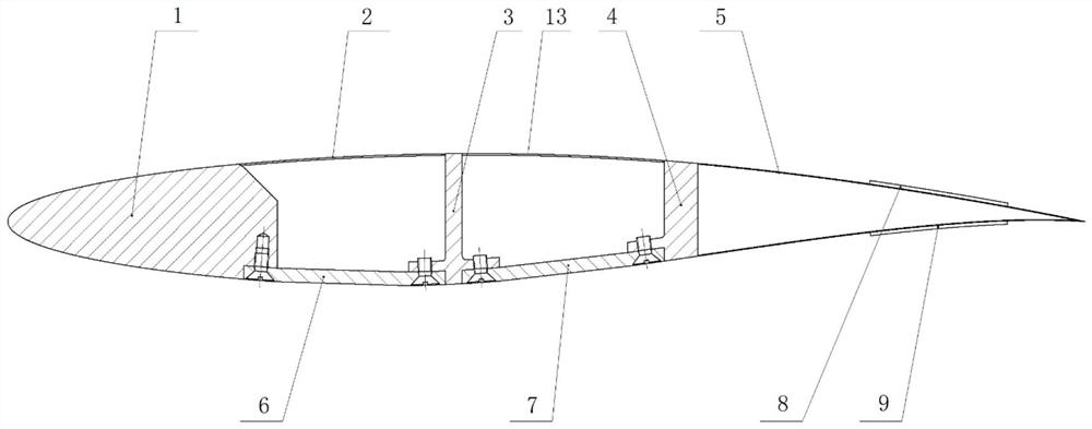
[0031] The installation process of the deformation wing based on the intelligent drive device of the present embodiment is as follows:

[0032] The front memory alloy intelligent driving device 6 and the rear memory alloy driving device 7 are installed under the deformed wing as the lower surface of the wing. The shape memory alloy driving device 7 is respectively connected to the middle partition 3 and the rear partition 4 by screws;

[0033] The skin I2 is connected to the leading edge 1 of the wing by screws, the skin II13 is connected to the middle partition 3 and the rear partition 4 by screws, and the empennage 5 is connected to the rear partition 4 by screws;

[0034] The upper piezoelectric intelligent driving device 8 and the lower piezoelectric intelligent driving device 9 are pasted on the upper surface and the lower surface of the empennage 5 respectively.


PUM


Abstract

The invention discloses a deformable wing based on an intelligent driving device. A framework of the deformable wing comprises a wing leading edge, a middle partition plate, a rear partition plate andan empennage which are sequentially arranged from front to back. A front shape memory alloy driving device between the wing leading edge and the middle partition plate forms a lower surface I of thewing, and the skin I covering the wing leading edge and the middle partition plate forms an upper surface I of the wing; a rear shape memory alloy driving device between the middle partition plate andthe rear partition plate forms the lower surface II of the wing, and the skin II covering the middle partition plate and the rear partition plate forms an upper surface II of the wing; the upper surfaces and the lower surfaces of the wings are in smooth transition; the deformable wing upper surface and the deformable wing lower surface are intersected at the rear edge of the empennage; and the upper surface and the lower surface of the empennage are provided with an upper piezoelectric intelligent driving device and a lower piezoelectric intelligent driving device respectively. The deformablewing has the advantages of compact structure, few driving elements, high driving capacity and continuous deformable wing surface, and can be popularized and applied to the structural design of wing camber deformation.

Description

technical field [0001] The invention belongs to the technical field of wind tunnel tests, and in particular relates to a deformable wing based on an intelligent driving device. Background technique [0002] Changes in the camber of the wing during flight will bring about changes in lift and drag. Changing the camber of the wing according to different flight stages will help improve the flight efficiency of the wing and achieve the purpose of increasing lift and reducing drag. [0003] At present, there are many devices used for wing camber deformation, but each has its advantages and disadvantages, and it is difficult to achieve perfection in terms of deformation range, mechanism weight, and mechanism efficiency. Existing wing camber deformation devices are mainly driven by motors, which drive connecting rods, sliders and other devices to perform translational and rotational movements. Due to the narrow space inside the wing, the performance of its driving components is ofte...

Claims


Application Information

Patent Timeline
Patent Type & Authority Applications(China)
IPC IPC(8): B64C3/44
CPCB64C3/44
Inventor 聂旭涛蔡清青高鑫宇陈万华张伟
Owner 中国空气动力研究与发展中心设备设计及测试技术研究所
Why Eureka
Try Eureka