Foundation pit supporting pile top crown beam structure and construction method thereof

A technology for foundation pit support and pile top, which is applied in foundation structure engineering, excavation, sheet pile wall, etc., can solve the problems of high construction cost, waste of manpower and material resources, etc., to ensure the firmness of the structure, save time, The effect of increasing flexibility

Pending Publication Date: 2021-03-26
京兴国际工程管理有限公司
View PDF5 Cites 0 Cited by
  • Summary
  • Abstract
  • Description
  • Claims
  • Application Information

AI Technical Summary

Problems solved by technology

The crown beam structure in the above-mentioned patent has the following disadvantages: Although it can meet certain usage requirements during construction, the process takes up a lot of time and the construction cost is high, and a lot of manpower and material resources are wasted at the same time

Method used


Image

  • Foundation pit supporting pile top crown beam structure and construction method thereof
  • Foundation pit supporting pile top crown beam structure and construction method thereof
  • Foundation pit supporting pile top crown beam structure and construction method thereof

Examples


Embodiment 1

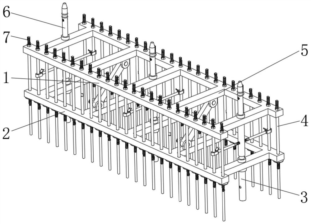
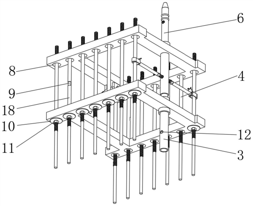
[0045] A foundation pit support pile crown beam structure, such as Figure 1-6 As shown, it includes a first frame body 1 and a second frame body 2, and the first frame body 1 and the second frame body 2 are provided with equidistantly distributed beams 5, and the first frame body 1 and the second frame body The outer wall of the bottom of the frame body 2 is provided with evenly distributed assembly sockets 8, and the first fixed rod 4 and the second fixed rod 18 are respectively inserted in the assembly sockets 8, and the position of the second fixed rod 18 is uniform Corresponding to 5, the bottom of the first fixed rod 4 and the second fixed rod 18 are uniformly provided with a tail rod 33, and a bearing thread 34 is arranged between the tail rod 33 and the first fixed rod 4 and the second fixed rod 18 , the diameter of the tail rod 33 is smaller than the size of the bearing thread 34, the bearing nut 11 is installed on the outer wall of the bearing thread 34, the top of t...

Embodiment 2

[0054] A construction method for foundation pit support pile top crown beam structure, such as Figure 1-6 shown, including the following steps:

[0055] S1: pre-embed the first fixing rod 4 and the second fixing rod 18 with the bearing nut 11 and the ring gasket 10 through the tail rod 33;

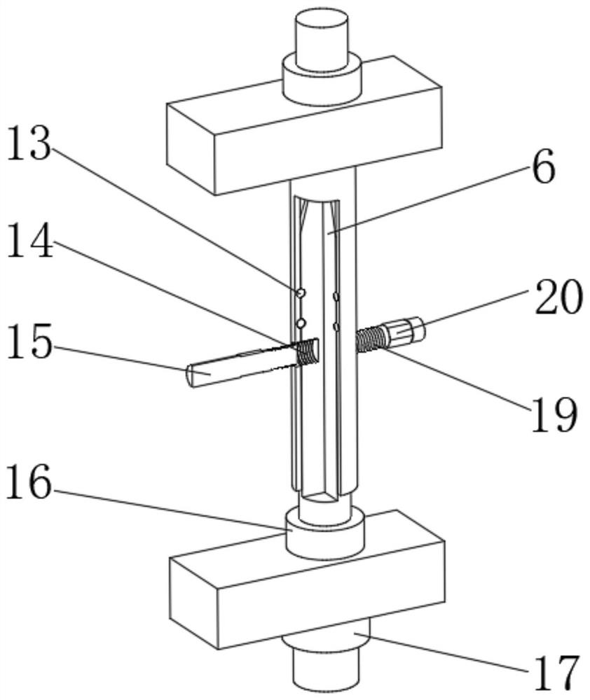
[0056] S2: Disassemble and assemble the connecting rod 6 and the connecting sleeve 3 according to the construction requirements;

[0057] S3: Put the second frame body 2 on the first fixed rod 4 and the second fixed rod 18, so that the first fixed rod 4 and the second fixed rod 18 pass through the assembly socket 8 of the second frame body 2;

[0058] S5: Put the socket piece 22 on the second fixing rod 18;

[0059] S4: put the first frame body 1 on the first fixed rod 4 and the second fixed rod 18, so that the first fixed rod 4 and the second fixed rod 18 pass through the assembly socket 8 of the first frame body 1; at the same time The connecting sleeve 3 of the first frame body 1 is...


PUM


Abstract

The invention discloses a foundation pit supporting pile top crown beam structure and a construction method thereof, and relates to the technical field of foundation pit supporting pile top crown beamstructures. In order to facilitate construction, the top crown beam structure specifically comprises a first frame body and a second frame body, cross beams distributed at equal intervals are arranged on the first frame body and the second frame body, assembly inserting holes distributed evenly are formed in the outer walls of the bottoms of the first frame body and the second frame body, a firstfixing rod and a second fixing rod are inserted into the assembly inserting holes respectively, and the second fixing rods correspond to the cross beams in position. By arranging the first frame body, the second frame body and other structures, the first frame body and the second frame body can be used as a main frame for supporting during installation, the structural firmness is guaranteed, a large amount of steel bar erecting time is saved, and the construction period is effectively shortened; and by arranging connecting rods, connecting sleeves and other structures, a user can disassembleand assemble according to the required height, so that multi-layer erection is achieved, and the flexibility is improved.

Description

technical field [0001] The invention relates to the technical field of foundation pit support pile crown beam structure, in particular to a foundation pit support pile crown beam structure and a construction method thereof. Background technique [0002] The crown beam of foundation pit supporting piles is a continuous beam arranged on the top of the supporting structure around the foundation pit; its function is to connect all the pile foundations together to prevent the top edge of the foundation pit from collapsing. At present, the general foundation pit supports The crown beams of protective piles are mostly cast-in-place operations. Although they can meet certain usage requirements, the process takes time and the construction costs are high, and a lot of manpower and material resources are wasted. [0003] After searching, the Chinese patent application number is CN201822122869.X, which discloses a hat-shaped composite steel sheet pile top-crown beam structure for founda...

Claims


Application Information

Patent Timeline
Patent Type & Authority Applications(China)
IPC IPC(8): E02D17/04E02D5/22
CPCE02D17/04E02D5/22
Inventor 闫慧谢岩李晓龙
Owner 京兴国际工程管理有限公司
Why Eureka
Try Eureka