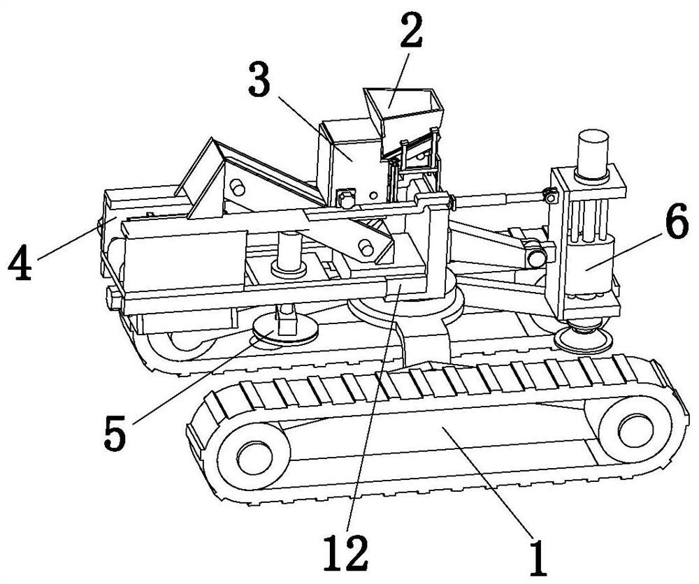
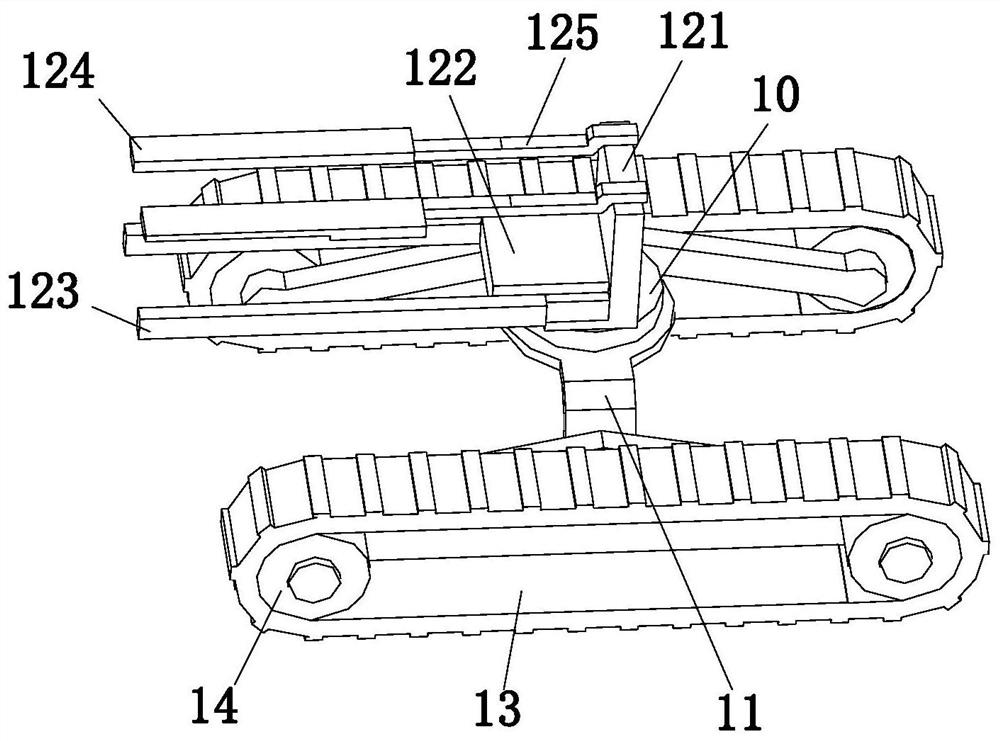
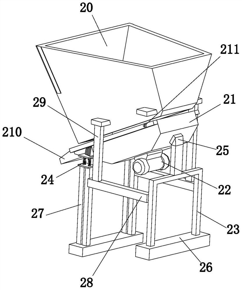
Landfilling system for mining area restoration and landfilling process of system

A technology for mining areas and conveying systems, which is used in fillings, mining equipment, safety devices, etc., can solve the problems of slow, sparse, and unenvironmental backfilling efficiency, and achieve the effect of avoiding material accumulation and enhancing stability.

Inactive Publication Date: 2021-03-26
王常浩
View PDF0 Cites 4 Cited by
  • Summary
  • Abstract
  • Description
  • Claims
  • Application Information

AI Technical Summary

Problems solved by technology

[0003] In the traditional technology, for the landfilling of pits in coal mining areas, the muck and gravel are directly dumped into the mine pit by the muck truck, and then the muck and gravel for backfilling are slowly pushed to various places by bulldozers, dump trucks, excavators, etc. The area to be buried is then rolled and tamped with a compactor, so that large-scale slag and gravel are backfilled into the pit backfill area, which will not only lead to unstable air strikes between the backfill materials, which are relatively sparse, but also have a very high backfill efficiency. Slow, takes a lot of time to level the cloth
Even if some mining pit areas use crushing stations to crush the dregs and gravels that will be backfilled, and then transport them to the site for dumping, this will increase the hazards of dust during transportation, which is not environmentally friendly and greatly reduces work. efficiency, and some mine areas are limited, and it is not suitable for multiple large-scale machines to operate at the same time, which is very inconvenient, so we need to design a flexible operation, wide application range, high landfill efficiency, good landfill effect, and good landfill A device and a landfill method with low burial operation cost, uniform and compact distribution of backfill muck and gravel

Method used


Image

  • Landfilling system for mining area restoration and landfilling process of system
  • Landfilling system for mining area restoration and landfilling process of system
  • Landfilling system for mining area restoration and landfilling process of system

Examples


Embodiment Construction

[0036] The technical solutions of the present invention will be clearly and completely described below in conjunction with the accompanying drawings. Apparently, the described embodiments are some of the embodiments of the present invention, but not all of them.

[0037] The components of the embodiments of the invention generally described and shown in the figures herein may be arranged and designed in a variety of different configurations. Accordingly, the following detailed description of the embodiments of the invention provided in the accompanying drawings is not intended to limit the scope of the claimed invention, but merely represents selected embodiments of the invention.

[0038] Based on the embodiments of the present invention, all other embodiments obtained by persons of ordinary skill in the art without making creative efforts belong to the protection scope of the present invention.

[0039] In the description of the present invention, it should be noted that the...


PUM


Abstract

The invention discloses a landfilling system for mining area renovation and a landfilling process of the system, and belongs to the technical field of coal mine pit backfilling. The landfilling systemcomprises an advancing system, a vibration feeding system, a crushing and conveying system, a screening and distributing system, a grinding system and a tamping system; and the advancing system is arranged on the pit face of a mine pit, the vibration feeding system is arranged in the middle of the top of the advancing system, the crushing and conveying system is arranged at the discharging end ofthe vibration feeding system, the screening and distributing system is installed on the lower portion of the discharging end of the crushing and conveying system, the grinding system is arranged between the crushing and conveying system and the screening and distributing system, and the tamping system is arranged at the end, away from the grinding system, of the advancing system. By means of allthe arranged systems, vibration feeding, crushing, screening and distributing, paving and tamping operation can be conducted on backfill materials, the materials can be backfilled into the mine pit more tightly and compactly, and the serious consequence that filling materials in a backfill area are too loose, and consequently land subsidence is caused is prevented.

Description

technical field [0001] The invention relates to the technical field of coal mine pit backfilling, in particular to a landfill system and a landfill process for mine restoration. Background technique [0002] Coal mine goaf backfill Coal mine goaf refers to the cavity or cavity left after the mining of underground coal or coal gangue in the process of coal mine operation. If the coal mine goaf is not reinforced in time and is not backfilled, it will collapse after a long time, causing ground subsidence, forming a subsidence pit on the surface, and making farmland impossible to cultivate. According to survey statistics, over the years the area of ​​land subsidence due to mining in our country has reached 10,000 mu, and every 10,000 tons of coal mined will have mu of ground facing subsidence. At present, coal gangue backfilling is mainly used for backfilling coal mine goafs in my country. Coal gangue is solid waste discharged during the coal mining process and coal washing pr...

Claims


Application Information

Patent Timeline
Patent Type & Authority Applications(China)
IPC IPC(8): E21F15/00E21F15/06B02C4/08B02C4/28B02C21/02B02C23/10
CPCB02C4/08B02C4/286B02C21/026B02C23/10E21F15/00E21F15/06
Inventor 不公告发明人
Owner 王常浩
Why Eureka
Try Eureka