Measuring system and measuring method

A measurement system and technology for detecting light, applied in the field of measurement, can solve the problems of long test time, influence of precision and accuracy, and large labor cost, so as to compensate for the instability of the optical path, improve the adjustment accuracy, and improve the system performance.

Pending Publication Date: 2021-03-26
SKYVERSE TECH CO LTD
View PDF16 Cites 1 Cited by
  • Summary
  • Abstract
  • Description
  • Claims
  • Application Information

AI Technical Summary

Problems solved by technology

In the prior art, the spatial optical path is used to measure the film thickness, but the adjustment of the spatial optical path is cumbersome. For example, if one device is fine-tuned, other devices must be adjusted accordingly, otherwise the precision and accuracy will be seriously affected.
In this way, the labor cost is high and the test time is long
In addition, the spatial optical path is susceptible to interference, and it is difficult to implement measurement in environments with strong electromagnetic interference or inflammable and explosive environments, resulting in poor stability of the measurement system and weak anti-interference ability

Method used


Image

  • Measuring system and measuring method
  • Measuring system and measuring method
  • Measuring system and measuring method

Examples


Embodiment Construction

[0060] In order to enable those skilled in the art to better understand the solution of the present application, the technical solution in the embodiment of the application will be clearly and completely described below in conjunction with the accompanying drawings in the embodiment of the application. Obviously, the described embodiment is only It is a part of the embodiments of this application, not all of them. Based on the embodiments in this application, all other embodiments obtained by persons of ordinary skill in the art without making creative efforts belong to the scope of protection of this application.

[0061] System embodiment

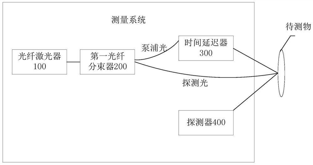
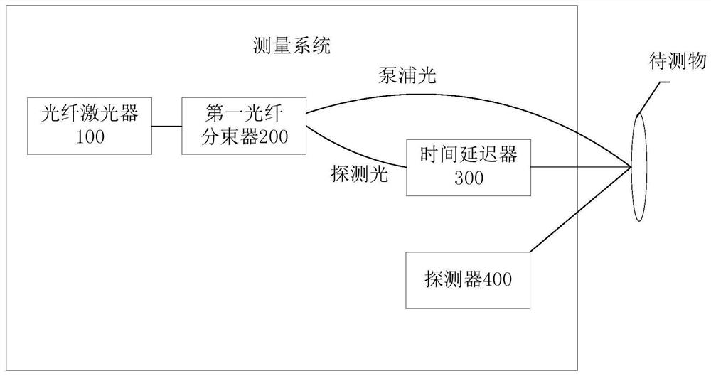
[0062] figure 1 It is a schematic structural diagram of a measuring system provided in the embodiment of this application. Such as figure 1 As shown, the measurement system includes: a fiber laser 100 , a first fiber beam splitter 200 , a time delayer 300 and a detector 400 . The following is an introduction to the connection relati...


PUM


Abstract

The invention discloses a measuring system and a measuring method. The system comprises an optical fiber laser, a first optical fiber beam splitter, a time delayer and a detector. The optical fiber laser generates a pulse light beam, and the first optical fiber beam splitter splits the pulse light beam into pump light and probe light. The time delayer enables the delay time between the pump lightand the probe light to be adjustable. And the two paths of light are finally emitted into an object to be measured. The detector is used for obtaining signal light formed by reflection of the detection light through the to-be-detected object in multiple different delay time, and obtaining detection information according to the signal light. Therefore, the photoacoustic measurement of the to-be-measured object is realized by using the measurement system. Part of optical paths in the system are realized through optical fibers, the optical paths of the optical fibers have the advantages of softness, randomly changeable shapes, long transmission distance and suitability for various severe environments with strong electromagnetic interference, flammability, explosiveness and the like, and the stability and the anti-interference capability of the system are improved. Tedious work such as collimation adjustment and the like is omitted in an optical fiber light path, the device adjustment convenience in the measurement process is improved, and the test time is shortened.

Description

technical field [0001] The present application relates to the field of measurement technology, in particular to a measurement system and a measurement method. Background technique [0002] Photoacoustic film thickness measurement is a precise optical measurement technology. The film thickness measurement range is 50A ~ 10um, and the accuracy can reach 0.1A. In the prior art, the spatial optical path is used to measure the film thickness, but the adjustment of the spatial optical path is cumbersome. For example, if one device is fine-tuned, other devices must be adjusted accordingly, otherwise the precision and accuracy will be seriously affected. In this way, the labor cost is large and the test time is long. In addition, the spatial optical path is susceptible to interference, and it is difficult to implement measurement in an environment with strong electromagnetic interference or inflammable and explosive environments, resulting in poor stability of the measurement syste...

Claims


Application Information

Patent Timeline
Patent Type & Authority Applications(China)
IPC IPC(8): G01B11/06
CPCG01B11/0625
Inventor 陈鲁白园园马砚忠
Owner SKYVERSE TECH CO LTD
Why Eureka
Try Eureka