Rigid body rotational inertia tester and test method

A rigid body rotation and tester technology, applied in static/dynamic balance testing, machine/structural component testing, instruments, etc., can solve problems that are not conducive to students' comprehensive analysis ability and scientific exploration spirit, inability to understand testing and control methods, Problems such as outdated testing and control methods, to achieve the effect of improving scalability, reducing repetitive actions, and real-time data collection

Pending Publication Date: 2021-03-26
HUNAN INSTITUTE OF ENGINEERING
View PDF0 Cites 2 Cited by
  • Summary
  • Abstract
  • Description
  • Claims
  • Application Information

AI Technical Summary

Problems solved by technology

[0005] The measurement accuracy of the traditional three-wire pendulum rigid body moment of inertia tester is not high, and the data results are greatly affected by the experimenter's operation methods, and the test and control methods are outdated, out of touch with modern test technology, making students inefficient in experimental learning and unable to Understanding advanced testing and control methods is not conducive to cultivating students' comprehensive analysis ability and scientific exploration spirit

Method used


Image

  • Rigid body rotational inertia tester and test method
  • Rigid body rotational inertia tester and test method
  • Rigid body rotational inertia tester and test method

Examples


Embodiment Construction

[0032] The present invention will be further described below in conjunction with the accompanying drawings and embodiments.

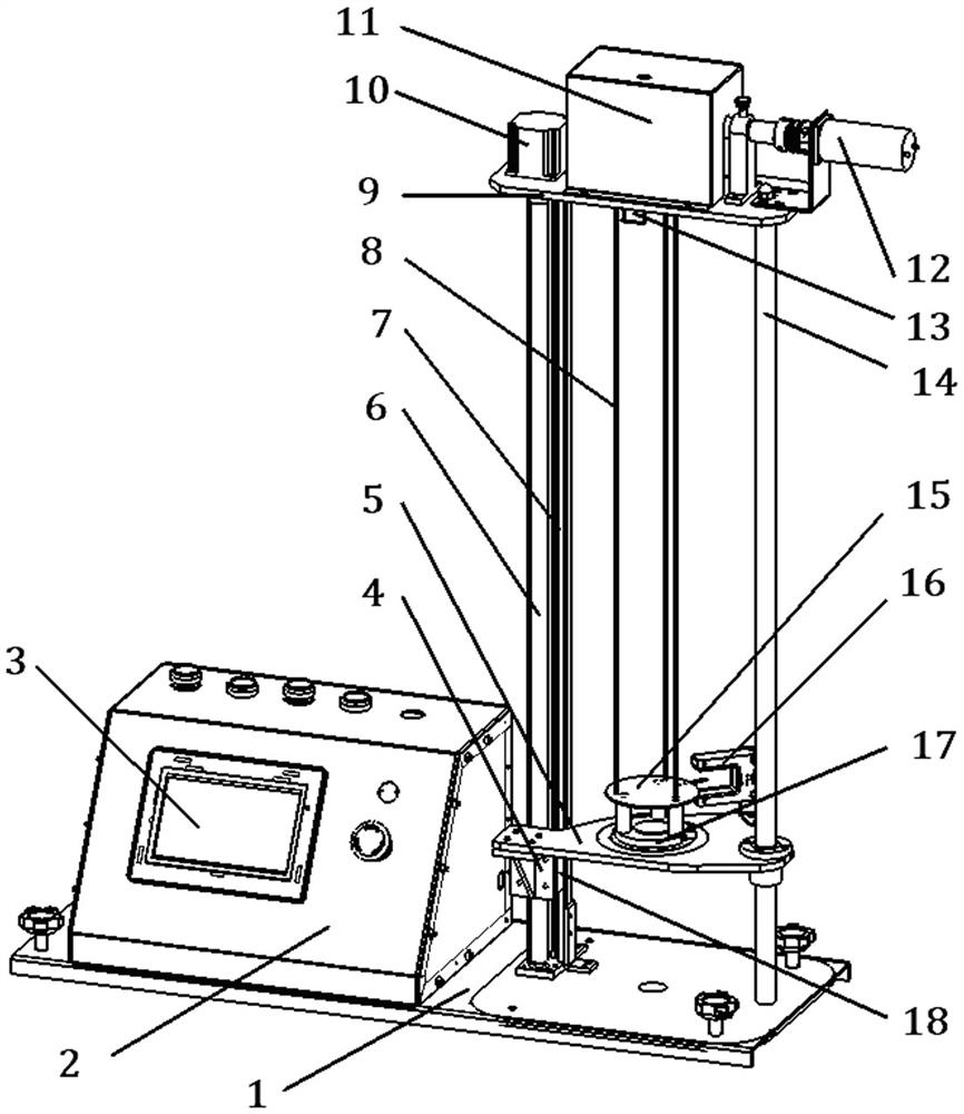
[0033] Such as figure 1As shown, a rigid body moment of inertia tester includes a horizontally arranged base plate 1, a three-wire pendulum device is placed on the right side of the base plate 1, a measurement and control system is placed on the left side of the base plate 1, and the three-line pendulum device includes a support rod 14 and an upper beam plate 9 , three cycloids 8, line length measurement and control device, lower swing plate 15, movable test platform 5, test platform lifting mechanism, a support rod 14 is vertically fixed on the right side of the base plate 1, and a screw support frame is vertically fixed in the middle of the base plate 1 7. The upper ends of the support rod 14 and the screw support frame 7 are horizontally connected to the upper beam plate 9, and the middle part of the upper beam plate 9 is provided with three first sm...


PUM


Abstract

The invention discloses a rigid body rotational inertia tester which comprises a horizontally arranged base plate, a three-line pendulum device arranged on the right side of the base plate and a measurement and control system arranged on the left side of the base plate, and the three-line pendulum device comprises a support rod, an upper cross beam plate, three cycloids, a line length measurementand control device, a lower swing disc, a movable test platform and a test platform lifting mechanism. A photoelectric sensor and an angle positioner are arranged on the movable test platform, and themeasurement and control system is connected with the wire length measurement and control device, the test platform lifting mechanism and the photoelectric sensor. The cycloid length of the three-linependulum device can be set and adjusted according to requirements, the expansibility is high, and the experiment efficiency is greatly improved through motor control; experiment efficiency is increased greatly; in addition, the angle positioner can control the swinging angle of the lower swing disc to be smaller than 6 degrees, a circular mirror surface is installed in the center of the upper surface of the tray, nine equidistant concentric circles are marked on the surface of the lower swing disc, so that it is guaranteed that the center of the lower swing disc coincides with the center of ameasured rigid body rotating shaft, and experimental data are more accurate.

Description

technical field [0001] The invention relates to an experimental teaching device for college physics and theoretical mechanics courses, in particular to a rigid body moment of inertia tester and a test method. Background technique [0002] Moment of inertia is the measure of inertia when a rigid body rotates about an axis of rotation. The role of moment of inertia in rotational dynamics is equivalent to the mass in linear dynamics. It can be understood as the inertia of an object for rotational motion and is used to establish the relationship between multiple physical quantities such as angular momentum, angular velocity, torque, and angular acceleration. [0003] The moment of inertia of a rigid body is related to the shape of the rigid body, the mass distribution and the position of the rotating shaft. The moment of inertia of a rigid body is often used in dynamic calculations of various motions and has important physical significance. It is an important parameter in scien...

Claims


Application Information

Patent Timeline
Patent Type & Authority Applications(China)
IPC IPC(8): G01M1/10
CPCG01M1/10
Inventor 刘兰罗跃平林天舒蒋嵘
Owner HUNAN INSTITUTE OF ENGINEERING
Why Eureka
Try Eureka