Stroboscopic stepped illumination defect detection system

A defect detection and step-by-step technology, which is applied in the direction of optical test defects/defects, measuring devices, instruments, etc., can solve problems such as low light source usage, limited, and types of defects, and achieve the effect of improving shooting capabilities

Active Publication Date: 2021-03-26
CASI VISION TECH (BEIJING) CO LTD +1
View PDF9 Cites 6 Cited by
  • Summary
  • Abstract
  • Description
  • Claims
  • Application Information

AI Technical Summary

Problems solved by technology

3D vision technology includes binocular vision, structured light, TOF (time of flight), triangular distance measurement, laser radar, etc. These technologies are currently widely used in three-dimensional physical recognition, measurement, and positioning, but they are rarely used in defect detection. And it is also difficult to meet the micron-level high-precision requirements of 3C products
[0009] However, in the prior art, the images of the four scenes (reflected bright field, reflected dark field, transmitted bright field, and transmitted dark field) obtained by the detection system of the detected object through the line array camera often reflect limited defects, because the linear array The speed at which the camera takes pictures is fixed, and the driving current of the light source corresponding to the shooting angle is fixed. Therefore, it is often necessary to change the pulse width of the corresponding light source when shooting different defects, and the maximum pulse width of the light source is the exposure of the line scan camera. Time, no matter how wide the pulse width is, it has no effect on the line scan camera, so this greatly limits the number of pictures taken, and also limits the types of defect detection
Moreover, because the current of the driving circuit corresponding to a single light source is fixed, when changing the illumination angle to take pictures of different bright field or dark field, often this light source will not be used for each defect at the same time, so the utilization rate of the light source is very high. Low, fewer types of defects for simultaneous shooting
At this time, the number of light sources and cameras can only be increased to take the required photos or more types of defects, which increases the cost and complexity of the system

Method used


Image

  • Stroboscopic stepped illumination defect detection system
  • Stroboscopic stepped illumination defect detection system
  • Stroboscopic stepped illumination defect detection system

Examples


Embodiment 1

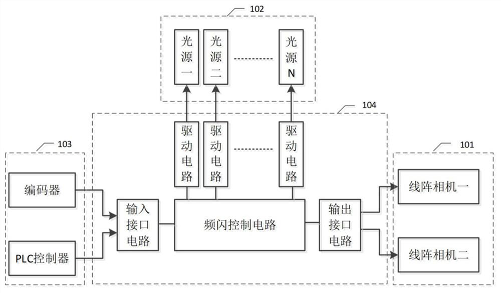
[0130] Such as figure 1 The above is a block diagram of the defect detection system for stroboscopic ladder lighting according to the embodiment of the present invention. Wherein, the defect detection system includes: an image extraction unit (101), a light and shade adjustment unit (102), a data processing unit (103) and a strobe control unit (104). The image extraction unit (101) has a plurality of cameras; the light and shade adjustment unit (102) further includes a plurality of light sources. The data processing unit (103) further includes an encoder and a PLC controller; the strobe control unit (104) further includes: a strobe control circuit, a drive circuit, an input interface circuit and an output interface circuit. The encoder generates a corresponding pulse code signal according to the speed of the mechanical rotation system; the PLC controller is a programmable controller, which generates an enabling signal to the strobe control unit after detecting the object to b...

Embodiment 2

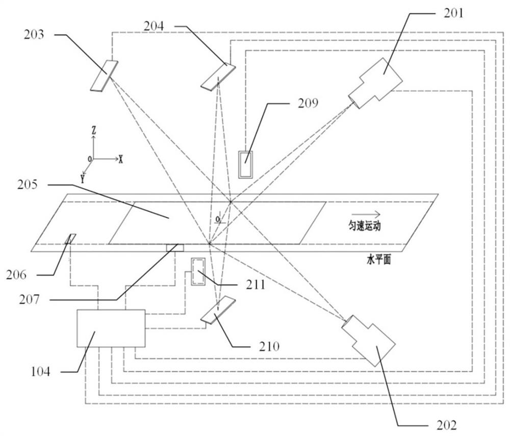
[0156] Such as image 3 As shown, it is a structural schematic diagram of a stroboscopic ladder lighting defect detection system that adds light source 3 to light source N for supplementary light according to the embodiment of the present invention. Among them, each component is: first camera 201, second camera 202, first light source 203, second light source 204, measured object 205, encoder 206, PLC controller 207, strobe control unit 104, third light source 209 , the fourth light source 210 , and the Nth light source 211 .

[0157] The first camera and the second camera are line scan cameras; the light source includes at least the first light source and the second light source; the encoder generates a corresponding pulse code signal according to the speed of the mechanical rotation system; the PLC controller is a programmable controller, which detects After reaching the measured object, an enabling signal is generated and provided to the stroboscopic control unit; the stro...

Embodiment 3

[0162] Such as Figure 4 as shown, Figure 4 It is a timing diagram of stroboscopic lighting imaging in the prior art. Wherein, when the period of the horizontal frequency signal is T, the first light source, the second light source, the first camera, and the second camera are used to detect and take pictures of four kinds of product defects under test. It can be seen that in the photo D1C1 of the photo taken in the reflected bright field, the first light source is turned on for T1, and the current value is I1 (the magnitude of the current value corresponds to the intensity of the light of the LED light source); in the photo D2C2 of the photo taken in the dark field of transmission , the second light source is turned on for T2 and current I2; in the photograph D1C2 of the transmitted bright field, the first light source is turned on for T3 and the current is I1; in the reflected dark field photograph D2C1, the second light source is turned on for T4 and the current is I2; It...


PUM


Abstract

The invention discloses a stroboscopic stepped illumination defect detection system, which is used for appearance defect detection of a product and comprises an image extraction unit (101), a brightness adjusting unit (102), a data processing unit (103) and a stroboscopic control unit (104). Wherein the image extraction unit (101) is connected with the stroboscopic control unit (104) and is used for acquiring stable and clear images in various transmission/reflection visual bright fields/dark fields; and the brightness adjusting unit (102) is connected with the stroboscopic control unit (104)and is used for setting various transmission/reflection visual bright fields/dark fields and converting in the various transmission/reflection visual bright fields/dark fields. According to the defectdetection system, under the condition that multiple cameras are adopted, the stroboscopic step control over the light sources is carried out, that is, the starting pulse width and the working currentvalue of the light sources are changed at the same time, and the multi-light-source cooperative work is adopted, so that the purpose of multi-directional imaging of various defects is achieved.

Description

technical field [0001] The invention relates to the technical field of machine vision defect detection, in particular to a machine vision appearance defect detection system and an implementation method with multiple cameras and strobe step lighting. Background technique [0002] The machine vision system converts the captured target into an image signal through an image capture device (CMOS and CCD sensors), and transmits it to a dedicated image processing system. The image system performs various operations on these signals to extract the features of the target. Its basic components usually include cameras, lenses, light sources, image acquisition cards, image processors, image processing software and algorithms. [0003] At present, machine vision systems have been deeply used in industrial inspection systems for identifying product information, measuring product sizes, and detecting product defects. Among them, since users have very high requirements on the appearance ...

Claims


Application Information

Patent Timeline
Patent Type & Authority Applications(China)
IPC IPC(8): G01N21/88G03B15/03
CPCG01N21/88G01N21/8806G03B15/03G01N2021/8838
Inventor 胡肖松骈冰
Owner CASI VISION TECH (BEIJING) CO LTD
Why Eureka
Try Eureka