Radar receiving and transmitting system adopting multi-layer microstrip connection

A radar transceiver and microstrip technology, applied in the field of signal transceiver, can solve the problems of increasing the volume and weight of the radar transceiver system, reducing the reliability of the radar transceiver system, and increasing the volume and weight of the transceiver system, so as to meet the requirements of volume weight and reliability design, The connection detection is fast and convenient, and the effect of simplifying the amount of equipment

Pending Publication Date: 2021-03-26
CHINA ELECTRONIC TECH GRP CORP NO 38 RES INST
View PDF6 Cites 0 Cited by
  • Summary
  • Abstract
  • Description
  • Claims
  • Application Information

AI Technical Summary

Problems solved by technology

[0003] The following problems exist in the blind-matching backplane plug-in connection method: 1) For a transceiver system, there are N modules outputting RF terminals, there are N / 2 RF connecting cables, and there are low-frequency cables for transmitting power and control Interconnecting cables all cause the volume and weight of the transceiver system to increase; 2) RF cables and low-frequency cables are closely interwoven, and the RF signals transmitted by RF cables have multiple frequencies. In order to reduce electromagnetic interference, various additional shielding materials and measures are also required. Increase the volume and weight of the system; 3) During the long-term use of multiple connecting cables, they are prone to wear and looseness under various environmental conditions. Whether it is the looseness of the cable port that affects the standing wave or the impact of cable wear on the index, it will The reliability of the system is greatly reduced; the above problems will increase the volume and weight of the radar transceiver system and reduce the reliability of the radar transceiver system
[0005] However, the above-mentioned published documents use multi-layer microstrip substrates to connect simply between components and device levels, and do not realize the connection between system levels.

Method used


Image

  • Radar receiving and transmitting system adopting multi-layer microstrip connection
  • Radar receiving and transmitting system adopting multi-layer microstrip connection
  • Radar receiving and transmitting system adopting multi-layer microstrip connection

Examples


Embodiment 1

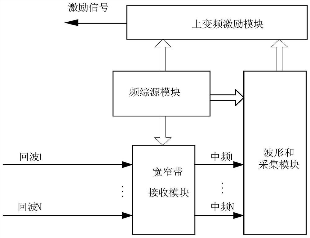
[0030] Such as figure 1 As shown, a radar transceiver system using multi-layer microstrip connection, each sub-module of the radar transceiver system includes a waveform and acquisition module, an up-conversion excitation module, a frequency synthesis source module, a wide and narrowband receiving module, and a multi-layer microstrip connection back board; the input of the up-conversion excitation module is connected to the waveform and the output of the acquisition module; each output of the frequency-synthesis source module is connected to the up-conversion excitation module, the wide-narrowband receiving module and the waveform and the acquisition module respectively The corresponding input terminals are connected; the wide and narrowband receiving module is a channel for processing the received mode signals, and its input comes from the signal synthesized by the antenna through the TR component; the described waveform and acquisition module provides various signals required...


PUM


Abstract

The invention discloses a radar receiving and transmitting system adopting multi-layer microstrip connection, relates to the technical field of signal receiving and transmitting in radar and countermeasure systems, and solves the problem of how to improve the reliability of the radar receiving and transmitting system while meeting the miniaturization and light weight of the radar receiving and transmitting system. The system comprises a waveform and acquisition module, an up-conversion excitation module, a frequency synthesis source module, a wide and narrow band receiving module and a multi-layer microstrip connection backboard. All the modules are connected through multiple layers of microstrip plates, so that the volume weight of the system is reduced; the module is connected with the multi-layer microstrip board in a blind matching mode, so that the module is convenient to assemble and replace, and the connection detection of the backboard is rapid and convenient. By adopting the design of the multi-layer microstrip plate, besides signal interconnection, the local oscillator and the clock signal can achieve multi-path power division inside, so that the equipment quantity is simplified, and channel expansion is easy to achieve; and the requirements of volume weight and reliability design of the radar system are met while the cable assembling work of the radar system is reduced.

Description

technical field [0001] The invention relates to the technical field of signal transmission and reception in radar and countermeasure systems, in particular to a radar transmission and reception system using multi-layer microstrip connections. Background technique [0002] The radar function thread mainly performs integrated surveillance tasks on the ground / sea surface. It needs to have various modes such as SAR, GMTI, and MMTI, as well as the ability to cooperate with electronic reconnaissance. It also has multiple working methods such as scanning while tracking, tracking, and search and tracking. And it can flexibly configure the number of channels in various modes, and the antenna system chooses a phased array antenna. In order to meet the cooperative operation requirements of synthetic aperture radar and electronic reconnaissance system, the active phased array antenna is covered with T / R components in the radiation unit, and the signal received by the antenna is amplifie...

Claims


Application Information

Patent Timeline
Patent Type & Authority Applications(China)
IPC IPC(8): G01S7/03
CPCG01S7/03
Inventor 袁同力束永江孙维佳丁勇
Owner CHINA ELECTRONIC TECH GRP CORP NO 38 RES INST
Why Eureka
Try Eureka