Multi-channel time-sharing multiplexing optical coupling device and using method

An optical coupling device, multi-channel technology, applied in the field of detection, can solve problems such as large space requirements and reduce the number of experimental devices, and achieve the effects of increasing accuracy, improving convenience, and reducing costs

Active Publication Date: 2021-03-26
HEFEI INSTITUTES OF PHYSICAL SCIENCE - CHINESE ACAD OF SCI
View PDF7 Cites 0 Cited by
  • Summary
  • Abstract
  • Description
  • Claims
  • Application Information

AI Technical Summary

Problems solved by technology

Solve the problem of large space requirements for multiple sets of signal measurement mechanism devices, and reduce the number of experimental devices

Method used


Image

  • Multi-channel time-sharing multiplexing optical coupling device and using method
  • Multi-channel time-sharing multiplexing optical coupling device and using method

Examples


Embodiment Construction

[0032] The technical solutions in the embodiments of the present invention will be clearly and completely described below in conjunction with the accompanying drawings in the embodiments of the present invention. Obviously, the described embodiments are only part of the embodiments of the present invention, not all of them. Based on the embodiments of the present invention, all other embodiments obtained by persons of ordinary skill in the art without making creative efforts belong to the protection scope of the present invention.

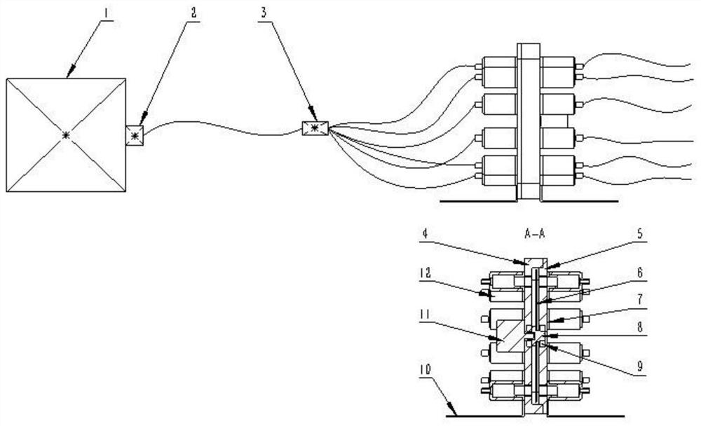
[0033] According to one embodiment of the present invention, a multi-channel time-sharing re-measurement optical coupling device is proposed, such as figure 1 A filter 2 is installed at the front end of the optical signal receiving and converting device 1 , and the filter 2 is connected to a multi-fiber 3 for connection between the optical signal receiving and converting device 1 and the collimating mirror 12 .

[0034] The bearing 9 is respectivel...


PUM


Abstract

The invention provides a multi-channel time-sharing multiplexing optical coupling device and a using method. The multi-channel time-sharing multiplexing optical coupling device comprises a square cavity, a square cavity cover plate, a baffle, a rotating shaft, a motor, a bearing, a bracket, a collimating mirror, a collimating mirror adapter, a one-to-many optical fiber, a filter and an optical signal receiving and converting device, the bearings are installed on the square cavity and the square cavity cover plate, the rotating shutter is locked on the rotating shaft through screws, the squarecavity cover plate and the square cavity are locked and sealed through screws and nuts, and the function of blocking stray light is achieved. The support is fixedly connected with the square cavity and the square cavity cover plate, and the collimating mirror and the collimating mirror adapter are locked and matched through threads and then locked on the square cavity and the square cavity cover plate through threads. The square cavity and the square cavity cover plate provide channel interfaces for a plurality of groups of signals, and meanwhile, a closed environment is formed in the device,so that the influence of other stray light on the signals is reduced; the rotating shutter is driven by the motor and the bearing to rotate, and a certain group of channels in the plurality of groupsof channels is selected to be opened, so that the transmission of the group of signals and the blocking of other groups of signals are realized.

Description

technical field [0001] The invention relates to the technical field of detection, in particular to a multi-channel time-division re-measurement optical coupling device and a usage method. Background technique [0002] EAST-NBI (Experimental Advanced Superconducting Tokamak-Neutral BeamInjector) spectral diagnostic system consists of three parts: DSS beam component diagnostic system, infrared thermometer monitoring system, and stray Da monitoring system. It can respectively complete the three functions of beam component measurement, tokamak high-field side beam spot center temperature monitoring and protection, and beam reionization loss monitoring and protection in the drift section of the neutral beam injector. All three systems involve the transmission of multiple sets of optical signals. [0003] At present, the transmission of multiple groups of optical signals is mainly that each group of signals is transmitted into the optical fiber through the light-receiving lens se...

Claims


Application Information

Patent Timeline
Patent Type & Authority Applications(China)
IPC IPC(8): G02B6/35H04B10/079
CPCG02B6/353G02B6/3558H04B10/079
Inventor 梁立振时超李超王昊明刘伟刘洋
Owner HEFEI INSTITUTES OF PHYSICAL SCIENCE - CHINESE ACAD OF SCI
Why Eureka
Try Eureka