Check patentability & draft patents in minutes with Patsnap Eureka AI!

A Method of LDO Circuit Layout

A circuit layout and circuit technology, which is applied in the direction of electrical digital data processing, instruments, calculations, etc., can solve the problems of no driving ability, circuit connection interference, and failure to achieve voltage stabilization effects, etc., to improve power supply rejection ratio and PSR guarantee Effect

Active Publication Date: 2022-05-24
SG MICRO
View PDF6 Cites 0 Cited by
  • Summary
  • Abstract
  • Description
  • Claims
  • Application Information

AI Technical Summary

Problems solved by technology

The difficulty of such an LDO circuit layout is that the purer voltage after RC filtering has no driving ability, and is easily disturbed by the internal wiring of the circuit. The weak parasitic capacitance will deteriorate the power supply rejection ratio, resulting in the failure to achieve the desired voltage regulation. Effect

Method used


Image

  • A Method of LDO Circuit Layout

Examples


Embodiment Construction

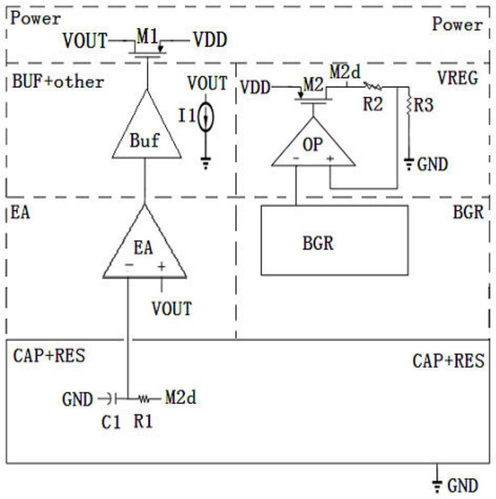
[0016] Below in conjunction with the accompanying drawings ( figure 1 ) to illustrate the present invention.

[0017] figure 1 It is a schematic structural diagram of implementing an LDO circuit layout method of the present invention. like figure 1 As shown, an LDO circuit layout includes an RC filter circuit CAP+RES, the RC filter circuit CAP+RES is arranged at the bottom, and an isolation ground wire is arranged around the RC filter circuit CAP+RES, and the isolation ground Above the line is the error amplifier EA, and the input end of the error amplifier EA is adjacent to the RC filter circuit CAP+RES up and down. The RC filter circuit CAP+RES includes a first resistor R1 and a first capacitor C1. One end of the first capacitor C1 is connected to the ground terminal GND, and the other end is connected to the negative input terminal of the error amplifier EA through the isolated ground wire. (-), the other path is connected to one end of the first resistor R1, and the ot...


PUM


Abstract

An LDO circuit layout method, by setting the RC filter circuit at the bottom, and setting the isolated ground wire around the RC filter circuit, the top of the isolated ground wire is an error amplifier, and the input terminal of the error amplifier is connected to the RC filter circuit. The filter circuits are adjacent to each other to prevent the RC filtered signal from being interfered, thereby improving the power supply rejection ratio of the LDO circuit.

Description

technical field [0001] The invention relates to LDO (low dropout regulator, low dropout linear regulator) technology, in particular to an LDO circuit layout method. Above the isolation ground wire is an error amplifier, and the input end of the error amplifier is adjacent to the RC filter circuit, so as to avoid the interference of the RC filtered signal, thereby helping to improve the power supply rejection ratio of the LDO circuit. Background technique [0002] The LDO circuit is a low dropout linear regulator circuit in an integrated circuit, which needs to have a high power supply rejection ratio (PSR) and low noise. The working principle of the LDO circuit is that the bandgap reference BGR generates a reference voltage, which is amplified by the regulator circuit to the desired voltage, and then filtered out by the RC filter circuit to generate a purer voltage. After the error amplifier EA, Buffer BUF and power tube POWER to improve its driving ability and resist exter...

Claims


Application Information

Patent Timeline
Patent Type & Authority Patents(China)
IPC IPC(8): G06F30/392
Inventor 林宇
Owner SG MICRO
Features
  • R&D
  • Intellectual Property
  • Life Sciences
  • Materials
  • Tech Scout
  • Unparalleled Data Quality
  • Higher Quality Content
  • 60% Fewer Hallucinations
Learn More