
Low-power-consumption high-PSRR band-gap reference circuit

A reference circuit and low power consumption technology, applied in the field of electricity, can solve the problems of increasing the complexity of the circuit design of the power consumption of the bandgap reference circuit, affecting the stability and accuracy of the bandgap reference circuit, and the loss of the function of the bandgap reference circuit. Convenient design, simple structure, and reduced chip area

Inactive Publication Date: 2016-08-31
西安电子科技大学昆山创新研究院 +1
View PDF5 Cites 12 Cited by
  • Summary
  • Abstract
  • Description
  • Claims
  • Application Information

AI Technical Summary

Problems solved by technology

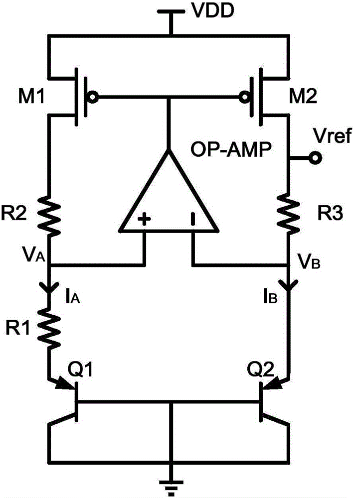
exist figure 1 In the circuit shown, due to the use of the operational amplifier, not only the core area of ​​the overall circuit is increased, but also the power consumption is greatly increased, which greatly increases the power consumption of the bandgap reference circuit and the complexity of the circuit design. At the same time, if the design of the operational amplifier is unreasonable, if its non-ideal factors such as offset cannot be well eliminated and suppressed, it will seriously affect the stability and accuracy of the bandgap reference, and may even cause the bandgap reference circuit function loss of

Method used


Image

  • Low-power-consumption high-PSRR band-gap reference circuit
  • Low-power-consumption high-PSRR band-gap reference circuit
  • Low-power-consumption high-PSRR band-gap reference circuit

Examples


Embodiment Construction

[0040] The bandgap reference circuit of the present invention is designed on the basis of the traditional bandgap reference circuit and combined with negative feedback control loop technology. The designed bandgap circuit not only has lower power consumption, but also has higher power supply rejection ratio (PSRR).

[0041] The present invention will be specifically introduced below in conjunction with the accompanying drawings and specific embodiments.

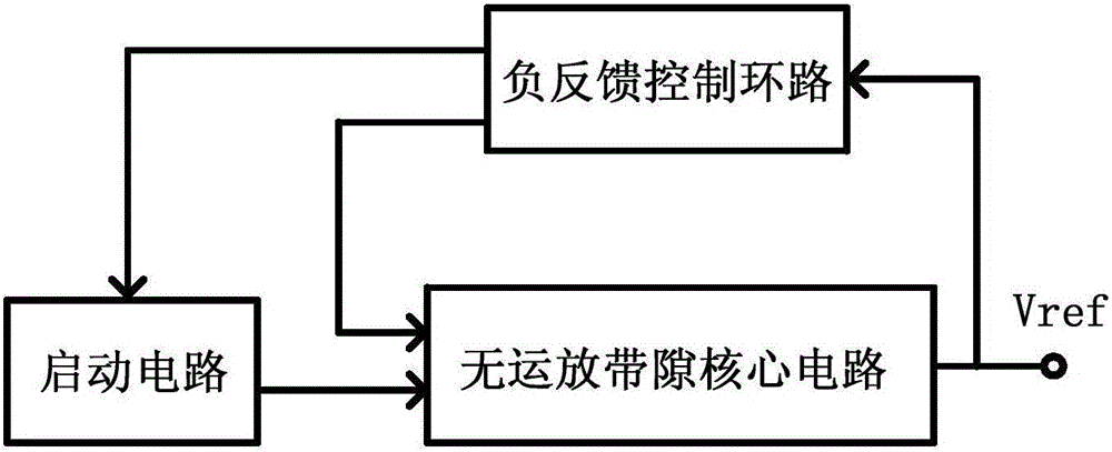
[0042] With reference to Fig. 2 (a) and Fig. 2 (b), the bandgap reference circuit of low power consumption high PSRR of the present invention is made up of no operational amplifier bandgap core circuit, start-up circuit and negative feedback control loop, wherein,

[0043] No op amp bandgap core circuit: used to realize the core function of the circuit and generate the required bandgap reference voltage.

[0044] Start-up circuit: used to complete the normal start-up of the bandgap reference circuit, so that the bandgap refe...


PUM


Abstract

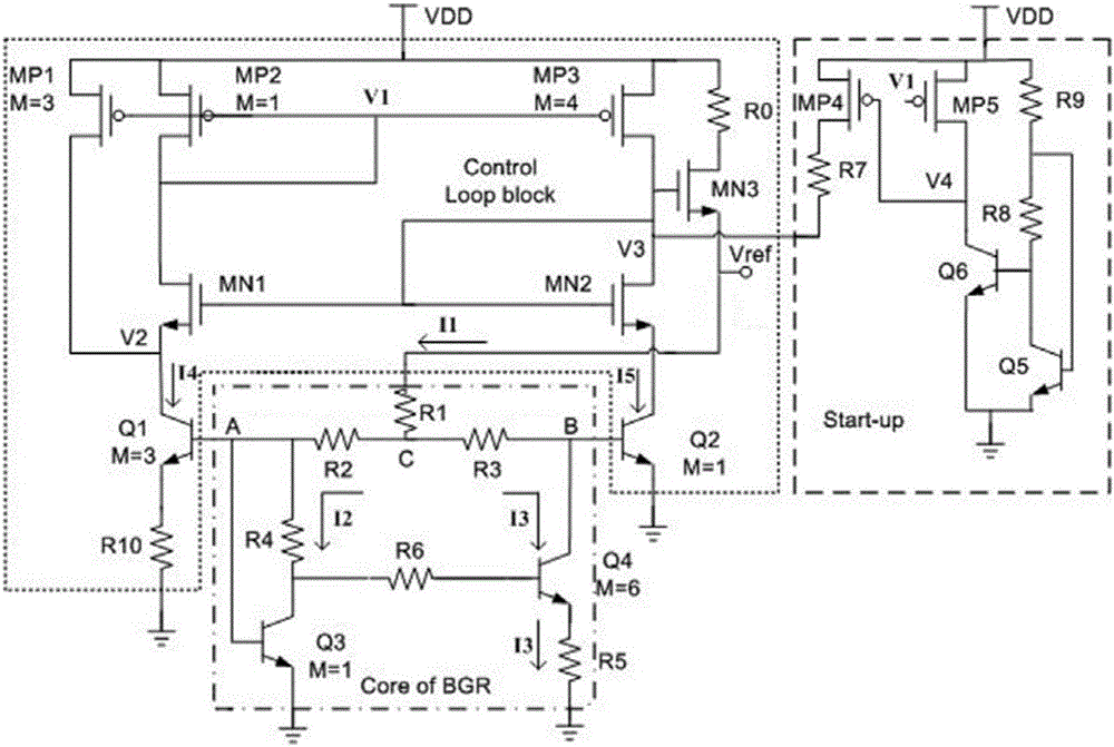
The invention discloses a low-power-consumption high-PSRR band-gap reference circuit. The low-power-consumption high-PSRR band-gap reference circuit is characterized by being composed of an operational-amplifier-free band gap core circuit, a starting circuit and a degeneration control loop; in the operational-amplifier-free band gap core circuit, the resistance value of a resistor R6 is far larger than that of a resistor R4 and that of a resistor R5, so that the base current of a transistor Q4 is low and even can be ignored, meanwhile, an operational amplifier is prevented from being used, the complexity of circuit design is lowered, and overall power consumption is further reduced; in the degeneration control loop, the voltage change of a node V2 and the electric potential errors of a node A and a node B are detected, degenerative voltages and a mirror image function of a current mirror are generated through a transistor MN2 in the loop, the influence of the supply voltage change and device mismatching on the circuits is restrained, and the stability of the band gap circuit is improved; in the starting circuit, a transistor MP4 triggers the band gap circuit to be started to work, therefore, the starting circuit can be fast switched off after the band gap circuit works normally, and power consumption of the circuit is reduced.

Description

technical field [0001] The invention relates to a bandgap reference circuit, in particular to a bandgap reference circuit with low power consumption and high PSRR, and belongs to the field of electrical technology. Background technique [0002] One of the main circuit structures of analog integrated circuits is the bandgap reference source, which is widely used in analog hybrid integrated circuits to provide a stable DC voltage that does not depend on power supply voltage and temperature changes. Traditional bandgap voltage references (attached figure 1 ) are commonly used in operational amplifiers. However, due to the low-voltage trend of CMOS technology, the typical value of the intrinsic gain of the transistor is about 20-30dB in deep submicron technology, which will lead to a decrease in the performance of the operational amplifier and cannot meet the The requirements of the bandgap reference circuit on its gain, bandwidth, etc., reduce the PSRR and its stability of the...

Claims


Application Information

Patent Timeline
IPC IPC(8): G05F1/567
CPCG05F1/567
Inventor 李娅妮庞光艺朱樟明杨银堂孙亚东
Owner 西安电子科技大学昆山创新研究院
Learn More