Chip transfer robot

A chip transfer and manipulator technology, applied in the direction of conveyor objects, electrical components, transportation and packaging, etc., can solve the problems of single function of the manipulator, low production efficiency, large workshop area, etc., to improve production efficiency, improve positioning accuracy, Effect of less workshop area

Active Publication Date: 2021-06-29
NINGBO QUNXIN MICRO-ELECTRONICS CO LTD
View PDF4 Cites 1 Cited by
  • Summary
  • Abstract
  • Description
  • Claims
  • Application Information

AI Technical Summary

Problems solved by technology

[0004] In the existing technology, due to the single function of the manipulator, two or more manipulators need to be used to transfer the chip, which occupies a large area of ​​the factory building, the production efficiency is low, and the cost is high

Method used


Image

  • Chip transfer robot
  • Chip transfer robot
  • Chip transfer robot

Examples


Embodiment Construction

[0026] As mentioned above, in the prior art, due to the single function of the manipulator, it is necessary to use two or more manipulators to transfer the chips, which occupies a large area of ​​the factory building, has low production efficiency and high cost.

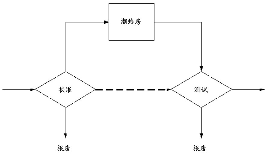
[0027] refer to figure 1 , figure 1 It is a schematic diagram of a working scene of a chip transfer manipulator in the prior art.

[0028] Specifically, such as figure 1 As shown in the straight line path, the chip transfer robot can be used in the chip measurement stage, including baking and testing the chip.

[0029] More specifically, the chip can be calibrated and burned first, and the abnormal bad chips are screened out and put into the bad product box for scrapping.

[0030] Then, use the robot to place the chip into the baking tray, send it into the hot flash room or humidification box for baking, so that the steam enters the chip through the acoustic space, so that various foreign objects on the chip appea...


PUM


Abstract

A chip transfer manipulator, comprising: a vertical manipulator column; a first manipulator bar, the first end of the first manipulator bar is connected to the manipulator post, and the second end of the first manipulator bar is provided with a first suction cup; second manipulator bar, the first end of the second manipulator bar is connected with the manipulator column, and the second end of the second manipulator bar is provided with a second sucker; the first manipulator bar and the manipulator There is a height difference between the connection position of the column and the connection position of the second manipulator lever and the manipulator column, so that the first manipulator lever and the second manipulator lever do not contact when rotating. The invention can make each manipulator rod can independently take and discharge materials, and will not collide with each other during work, realizes more complex operations, occupies less workshop area, improves production efficiency, and reduces costs.

Description

technical field [0001] The invention relates to the technical field of chip manufacturing, in particular to a chip transfer manipulator. Background technique [0002] In many semiconductor processes, it is necessary to use a finished chip transfer device to transfer finished chips. The existing finished chip transfer devices all include a vacuum suction manipulator, which utilizes the principle of vacuum suction to absorb the finished chip so as to transfer the finished chip to a desired position. [0003] In a specific application scenario, after the chip is calibrated and tested, the chip can be baked, and then a normal test can be performed. During this process, it is necessary to place the chip into the baking tray, and then retrieve the chip from the baking tray and transfer it to the testing machine, etc. [0004] In the prior art, due to the single function of the manipulator, two or more manipulators need to be used to transfer the chips, which occupies a large are...

Claims


Application Information

Patent Timeline
Patent Type & Authority Patents(China)
IPC IPC(8): H01L21/677H01L21/683H01L21/687
CPCH01L21/67706H01L21/67721H01L21/6838H01L21/687
Inventor 宋友奎
Owner NINGBO QUNXIN MICRO-ELECTRONICS CO LTD
Why Eureka
Try Eureka