Rotor assembly, motor and compressor
A component and rotor technology, which is applied in the field of compressors, can solve the problems of large oil discharge rate of compressors, and achieve the effect of reducing oil discharge rate and oil discharge rate.
- Summary
- Abstract
- Description
- Claims
- Application Information
AI Technical Summary
Problems solved by technology
Method used
Image

Examples
Embodiment 1
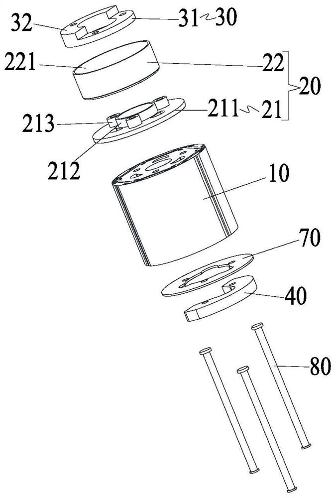
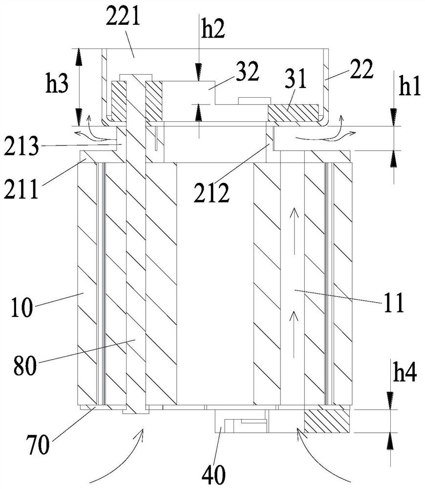
[0050] Such as figure 2 and image 3 As shown, the rotor assembly 2 includes a rotor core 10 and an oil deflector 20, wherein the rotor core 10 has a flow channel 11 for the oil-air mixture to flow in; the oil deflector 20 includes a first oil deflector seat 21 and an oil deflector The oil cap 22, the first oil retaining seat 21 is connected to the end face of the rotor core 10, the end face of the oil retaining cap 22 facing the rotor core 10 abuts against the first oil retaining seat 21 to seal the oil retaining cap 22 and the gap between the first oil deflecting seat 21.
[0051] The present application provides a rotor assembly with an oil retaining portion 20, which effectively reduces the oil discharge rate of the compressor on the premise of ensuring the working reliability of the compressor.
[0052] Specifically, by connecting the first oil deflector seat 21 of the oil deflector 20 to the end surface of the rotor core 10, at the same time, the end surface of the oi...
Embodiment 2
[0063] It should be noted that the difference between this embodiment and Embodiment 1 is that, as Figure 12 to Figure 14 As shown, the rotor assembly 2 also includes a second balance weight 40 and an oil shield 50, the second balance weight 40 is connected to the end surface on the other axial side of the rotor core 10; the oil shield 50 is set on the second balance weight The outer peripheral side of 40; the distance from the outer surface of the groove bottom of the receiving groove 221 to the end surface of the oil retaining seat body 211 away from the rotor core 10 is h1, where 0.5mm≤h1≤5mm. In this way, the setting of the oil deflector 50 avoids the sweeping effect of the first balance weight 30, which is beneficial to increase the flow rate of the oil-air mixture entering the flow channel 11 of the rotor core 10 from the lower cavity in the cylinder body 1, and further ensures a large amount of The oil and gas mixture can be separated from the oil and gas in the upper ...
Embodiment 3
[0065] Such as Figure 15 to Figure 20 As shown, the oil deflector 20 also includes a second oil deflector seat 23, the second oil deflector seat 23 is arranged between the first oil deflector seat 21 and the oil deflector cap 22, and the first end of the second oil deflector seat 23 protrudes A plurality of second support columns 231 are arranged in a one-to-one correspondence with the plurality of first support columns 213, and the second end of the second oil deflecting seat 23 abuts against the annular boss 212, The end surface of the second support column 231 abuts against the outer surface of the bottom of the receiving groove 221 . In this way, it is ensured that the compressor has a double-layer oil-repelling structure. In addition, the low-pressure effect between the second oil-repelling seat 23 and the oil-repelling cap 22 is used to introduce the oil-air mixture in the upper cavity of the cylinder 1 into the second oil-repelling seat 23 In the space between oil def...
PUM
 Abstract
Description
Claims
Application Information
 - R&D
- Intellectual Property
- Life Sciences
- Materials
- Tech Scout
- Unparalleled Data Quality
- Higher Quality Content
- 60% Fewer Hallucinations
Browse by: Latest US Patents, China's latest patents, Technical Efficacy Thesaurus, Application Domain, Technology Topic, Popular Technical Reports.
© 2025 PatSnap. All rights reserved.Legal|Privacy policy|Modern Slavery Act Transparency Statement|Sitemap|About US| Contact US: help@patsnap.com