Multi-user shared access receiver based on neural network and communication method thereof
A neural network and shared access technology, applied in neural learning methods, biological neural network models, neural architectures, etc., can solve problems such as high complexity, receiver bit error rate performance and detection performance need to be improved
- Summary
- Abstract
- Description
- Claims
- Application Information
AI Technical Summary
Problems solved by technology
Method used
Image

Examples
specific Embodiment approach 1
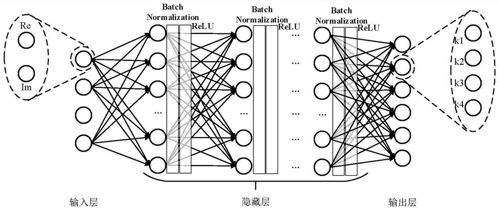
[0031] DETAILED DESCRIPTION OF THE PREFERRED EMBODIMENTS 1. A neural network-based multi-user shared access receiver, a neural network-based multi-user shared access receiver, which includes: a DNN model, the DNN model is located at the signal receiving end, and the DNN model includes an input layer, hidden layer and output layer;
[0032] The input layer is used to input data of K users;
[0033] The hidden layer is used to hide the data of K users;
[0034] The output layer is used to output data of K users;
[0035] Its characteristics are: the number of hidden layers in the DNN model is L, L is a positive integer l=1,...L, and the hidden layer of the first layer contains the connection weight matrix W l , bias vector b l and the activation function σ l , neurons in each layer use the same σ l The structure of the DNN model is expressed as:
[0036] σ L (W L σ L-1 (...σ 1 (W 1 x+b 1 )…)+b L ),
[0037] In the formula: x represents the input data to be processe...
specific Embodiment approach 2
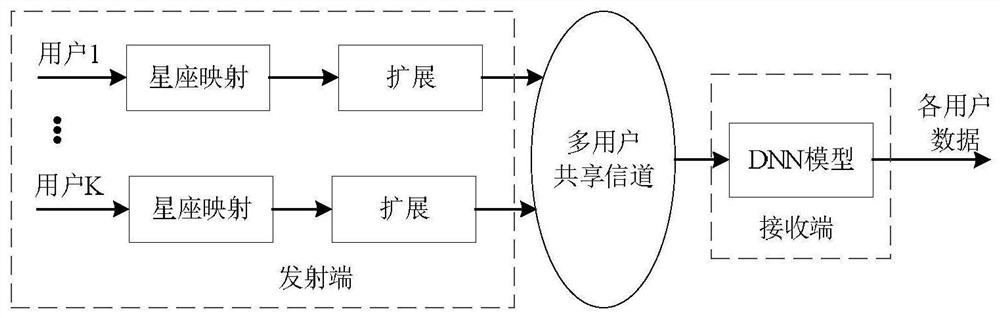
[0040] Specific embodiment two, the communication method of multi-user shared access receiver based on the neural network described in specific embodiment one: it is characterized in that: its signal transmission method:
[0041] Step 1. K users perform constellation mapping respectively to obtain K mapping results;
[0042] Step 2, respectively performing expansion processing on the K mapping results obtained in step 1 to obtain K expansion processing results;
[0043] Step 3. Transmitting the K extended processing results obtained in the step as transmission signals to the multi-user shared channel;
[0044] Its signal receiving method: the receiving end receives the transmitting signal transmitted by the transmitting end in the multi-user shared channel and sends it to the DNN model for processing;
[0045] Step 4: The DNN model outputs the original data of K users, and completes a neural network-based multi-user shared access receiver communication.
[0046] Principle: A...
PUM
 Abstract
Description
Claims
Application Information
 - R&D
- Intellectual Property
- Life Sciences
- Materials
- Tech Scout
- Unparalleled Data Quality
- Higher Quality Content
- 60% Fewer Hallucinations
Browse by: Latest US Patents, China's latest patents, Technical Efficacy Thesaurus, Application Domain, Technology Topic, Popular Technical Reports.
© 2025 PatSnap. All rights reserved.Legal|Privacy policy|Modern Slavery Act Transparency Statement|Sitemap|About US| Contact US: help@patsnap.com