Bending structure and joint function part using the same

A joint function and structure technology, which is applied in the field of curved structures and joint functions, can solve problems such as complex structures, and achieve the effects of simplified structure, constant movement, and stabilization

Pending Publication Date: 2021-03-26
NHK SPRING CO LTD
View PDF8 Cites 0 Cited by
  • Summary
  • Abstract
  • Description
  • Claims
  • Application Information

AI Technical Summary

Problems solved by technology

[0005] However, in the flexible member of Patent Document 1, a plurality of disc elements are engaged with each other, so there is a problem that the structure is complicated.

Method used


Image

  • Bending structure and joint function part using the same
  • Bending structure and joint function part using the same
  • Bending structure and joint function part using the same

Examples


Embodiment 1

[0045] [Structure of the curved structure]

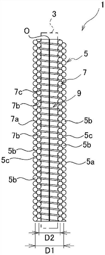
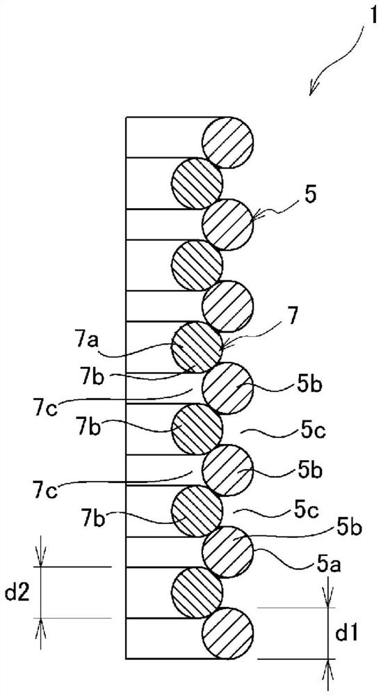
[0046] figure 1 is a cross-sectional view showing the bending structure of the flexible member according to Example 1 of the present invention, figure 2 It is an enlarged view showing its part.

[0047] The bending structure 1 is applied to, for example, a joint function part of a robot, a manipulator, or an actuator in various fields. The curved structure 1 is provided between the base of the joint functional part and the movable part, and supports the movable part so as to be displaceable with respect to the base by bending.

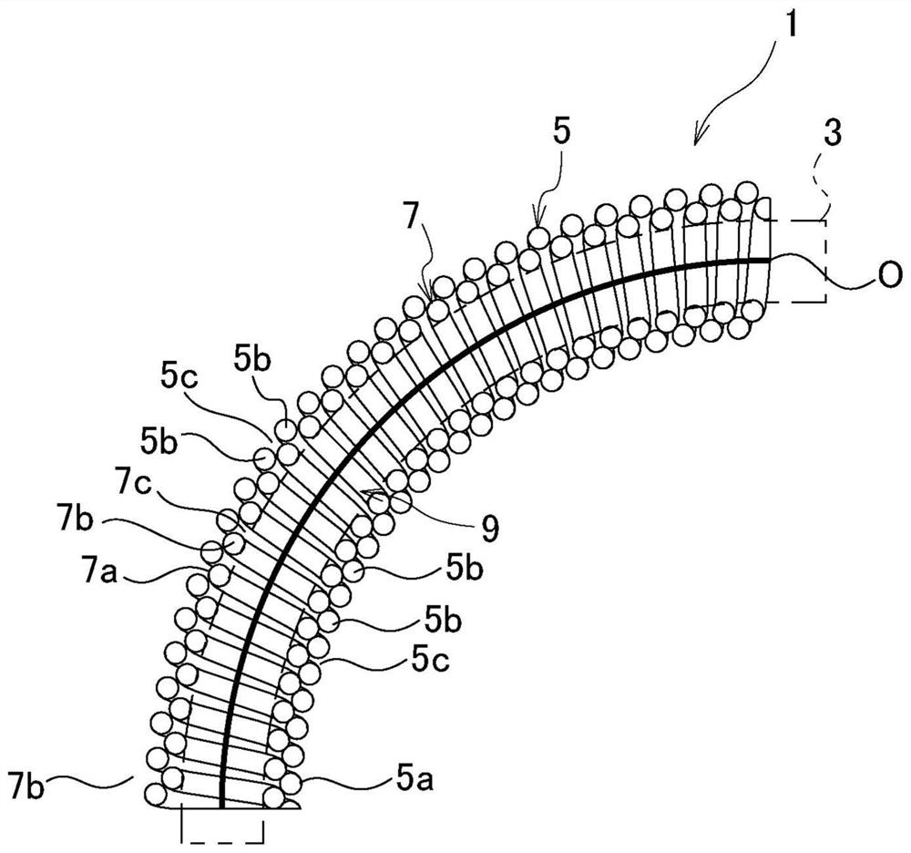
[0048] The curved structure 1 of the present embodiment has a double coil shape, and includes an outer coil portion 5 and an inner coil portion 7 . With this double coil shape, the bending structure 1 of the present embodiment can be bent with respect to the axial direction, and when bent by an external force, the inner diameter side of the bend contracts and the outer diameter side of the bend expands, ...

Embodiment 2

[0105] Figure 7 It is an enlarged cross-sectional view showing a part of the curved structure of Example 2. FIG. In addition, in Example 2, the same code|symbol is attached|subjected to the structure corresponding to Example 1, and the repeated description is abbreviate|omitted.

[0106] In the bending structure 1 of Example 2, the wire diameter d1 of the wire rod 5a of the outer coil part 5 and the wire diameter d2 of the wire rod 7a of the inner coil part 7 are different. In Example 2, the wire diameter d1 of the outer coil portion 5 is made larger than the wire diameter d2 of the inner coil portion 7 . In addition, the wire diameter d1 of the outer coil portion 5 can also be made smaller than the wire diameter d2 of the inner coil portion 7 .

[0107] Even if the structural body 1 is bent in this way so that the wire diameter d1 of the outer coil portion 5 and the wire diameter d2 of the inner coil portion 7 are different, the same functions and effects as those of the f...

Embodiment 3

[0109] Figure 8 It is an enlarged cross-sectional view showing a part of the curved structure of Example 3. FIG. In addition, in Example 3, the same code|symbol is attached|subjected to the structure corresponding to Example 1, and the repeated description is abbreviate|omitted.

[0110] In the bending structure 1 of Example 3, in a part of the axial direction of the outer coil part 5, the coil part 7b of the inner coil part 7 is in contact with the adjacent coil part 5b of the outer coil part 5, and is fitted to these coil parts 5b. between adjacent roll portions 5b.

[0111] That is, the inner coil portion 7 is formed to have a center diameter D2 (refer to figure 1 ) gradually decreases in the axial direction. As a result, the inner coil portion 7 is fitted between the adjacent winding portions 5b of the outer coil portion 5 only in a part of the axial direction as described above.

[0112] In addition, in this embodiment, the inner coil portion 7 and the outer coil por...


PUM


Abstract

Provided are a bending structure and a joint function part that make it possible to maintain sufficient flexibility and axial rigidity. The bending structure is provided with: an outer coil section 5comprising a wire 5a that is wound in a coil shape and that has a plurality of wound sections 5b in the axial direction; and an inner coil section 7 positioned within the outer coil section 5 and comprising a wire 7a that is wound in a coil shape and that comprises a plurality of wound sections 7b in the axial direction. The outer coil section 5 has a plurality of gaps 5c separating adjacent woundsections 5b from each other. The wound sections 7b of the inner coil section 7 are provided so as to correspond to the gaps 5c in the outer coil section 5, are brought into contact with the adjacentwound sections 5b of the outer coil section 5, and are fitted between the wound sections 5b.

Description

technical field [0001] The present invention relates to a curved structure used for a joint functional part of a robot or the like, and a joint functional part using the curved structure. Background technique [0002] Robots, manipulators, and actuators in various fields have systems with joint function parts. As a bending structure applied to such a joint function part, there is a flexible member described in Patent Document 1, for example. [0003] The flexible member of Patent Document 1 is configured by engaging a plurality of disk elements so as to be swingable with each other, and the entire bending operation is performed by the swinging of each disk element. [0004] The flexible member of this structure can smoothly perform the bending operation, and can ensure the rigidity with respect to the compression in the axial direction, and can realize the stabilization of the bending operation. [0005] However, since the flexible member of Patent Document 1 engages a plu...

Claims


Application Information

Patent Timeline
Patent Type & Authority Applications(China)
IPC IPC(8): B25J17/00A61B17/29
CPCA61B17/29A61B34/30A61B2017/00305A61B2017/00323A61B34/71A61B2034/305A61B2034/306B25J17/00A61B34/37A61B17/2909A61B2017/2918A61B2017/292A61B2017/2939B25J3/00B25J17/02A61B34/70A61B17/28B25J9/1075A61B2017/2905A61B2017/2908A61B2034/301
Inventor 平田贵史黑川真平保户田裕树
Owner NHK SPRING CO LTD
Why Eureka
Try Eureka