Gun in-place identification method

An identification method and gun technology, applied in the direction of electromagnetic audible signals, applications, time registers, etc., can solve problems such as the inability to link the alarm with the video monitor, the inability to select the identification method, and the inability to set the operating authority.

Inactive Publication Date: 2021-03-30
广州华洲信息科技有限公司
View PDF7 Cites 1 Cited by
  • Summary
  • Abstract
  • Description
  • Claims
  • Application Information

AI Technical Summary

Problems solved by technology

[0005] Aiming at the deficiencies of the prior art, the present invention provides a firearm in-position identification method, which can set the operation authority, select different identification methods, set the supplementary light, start the alarm, and can also connect the alarm with the video surveillance Through linkage with the device, you can know the detailed opening and closing conditions of the cabinet door and the drawer where the bullets are stored, record the time when the door is opened to retrieve the bullets and generate a detailed log, can detect whether the gun is in place, and can find out whether the gun has been dropped in time, which solves the problem The existing intelligent weapon room bullet cabinet cannot set the operation authority, and cannot choose different identification methods. When the identity verification fails, the alarm cannot be activated, nor can the alarm be linked with the video monitor, and the cabinet door and storage cannot be known. The detailed opening and closing of the bullet drawer does not record the time when the door is opened to take the bullets, which may easily lead to mistakes in management. It is impossible to know whether the guns in the cabinet are in place, and it is impossible to know whether the guns have been dropped.

Method used


Image

  • Gun in-place identification method
  • Gun in-place identification method
  • Gun in-place identification method

Examples


Embodiment Construction

[0037] The following will clearly and completely describe the technical solutions in the embodiments of the present invention with reference to the accompanying drawings in the embodiments of the present invention. Obviously, the described embodiments are only some, not all, embodiments of the present invention. Based on the embodiments of the present invention, all other embodiments obtained by persons of ordinary skill in the art without making creative efforts belong to the protection scope of the present invention.

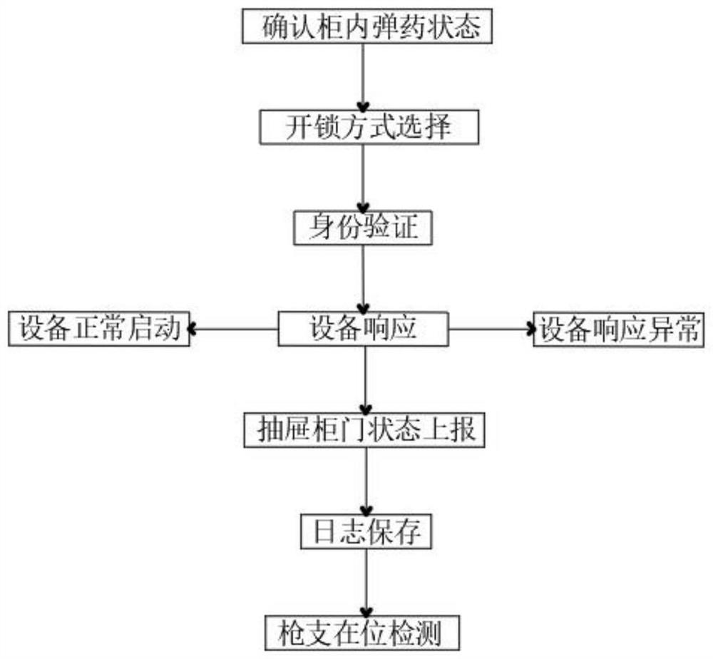
[0038] see Figure 1-4 , a firearm in-position identification method, including confirmation of ammunition status in the cabinet 1—unlocking method selection 2—identity verification 3—equipment response 4—drawer closing status report 5—log preservation 6—gun presence detection 7, the specific steps are as follows :

[0039] Confirm the ammunition status in the cabinet 1: You can check the bullets and images in the smart bullet cabinet in real time through the...


PUM


Abstract

The invention relates to the field of ordnance theft prevention, and discloses a gun in-place identification method. The method comprises the steps of confirming an ammunition state in a cabinet, selecting an unlocking mode, authenticating, responding to equipment, reporting a drawer closing state, storing a log and detecting a gun in place. According to the gun in-place identification method, theproblem that the cabinet door of an existing intelligent gun and bullet cabinet can only be controlled through a physical lock and a fingerprint coded lock is solved, the authority of an operator canbe set, an alarm can be started and linked with a video monitor, an electromagnetic lock and a bullet drawer lock of a cabinet door can be controlled through an intelligent control panel, different identity verification modes can be selected, a light supplementing lamp is turned on during identity verification, the identification accuracy can be guaranteed, and when the drawer and the cabinet door are closed, the closing state of the drawer and the cabinet door can be reported, so that the use time and frequency can be recorded and made into a log, the gun in-place state can be quickly detected, and emergency handling is facilitated.

Description

technical field [0001] The invention relates to the field of ordnance anti-theft, in particular to a firearm presence identification method. Background technique [0002] The intelligent weapon room bullet cabinet system is a system specially designed for the military to manage ordnance, involving communication Internet of Things, artificial intelligence, big data and other technologies, and has the advantages of good security, strong confidentiality, and high intelligence. [0003] There are some shortcomings in the existing intelligent weapon room bullet cabinets. Generally, only physical locks and fingerprint code locks are used to control the cabinet doors. There is no setting of operation authority, and different identification methods cannot be selected. When the authentication fails, the alarm cannot be activated. It is also impossible to link the alarm with the video monitor. In addition, it is impossible to know the detailed opening and closing of the cabinet door a...

Claims


Application Information

Patent Timeline
Patent Type & Authority Applications(China)
IPC IPC(8): A47B81/00A47B97/00H04N7/18G07C9/32G07C9/33G07C9/37G07C9/38G08B3/10G08B13/08
CPCA47B81/005A47B97/00H04N7/18G07C9/32G07C9/33G07C9/37G07C9/38G08B3/10G08B13/08A47B2220/0091
Inventor 丁胜华李镞陈松健段志波黄树声
Owner 广州华洲信息科技有限公司
Why Eureka
Try Eureka