Odor collecting system and method

A collection system and odor technology, applied in the direction of cleaning methods using gas flow, chemical instruments and methods, cleaning methods and utensils, etc., can solve the problem of large deviation of design values, difficulty in achieving precise control, and difficulty in achieving effective suction Negative pressure and other problems, to achieve the effect of precise collection and high control precision

Active Publication Date: 2021-03-30
HUNAN JUNXIN ENVIRONMENTAL PROTECTION CO LTD
5 Cites 0 Cited by

AI-Extracted Technical Summary

Problems solved by technology

[0004] (1) Odor point sources at the end of the main pipe are often unable to be effectively collected and some slight odor point sources are excessively collected. The actual air intake volume of each odor point source is difficult to reach the design value, or devi...

Method used

As shown in Figure 2, the odor collection system of the present embodiment comprises control unit and many collection branch pipes, and collection branch pipe is used to carry out odor collection to odor point source; Multiple point sources are divided into a plurality of regions , the collection sub-pipes corresponding to the point sources in each area are connected to a first-level main pipe, and one end of the collection main pipe is provided with a first-level fan, and each first-level fan is divided into multiple groups, and the first-level fans in each group are passed through two The first-level main duct is connected to the corresponding second-level fan, and so on, until all n-level fans are connected to the main fan through the main main duct; among them, the second-level fan to the n-level fan and the main fan are connected to at least one independe...

Abstract

The invention discloses an odor collecting system which comprises a control unit and a plurality of collecting branch pipes. A plurality of point sources are divided into a plurality of regions, the collecting branch pipes corresponding to the point sources in each region are connected with a primary main pipe, primary fans are arranged at one end of a collection main pipe, the primary fans are divided into a plurality of groups, the fans in each group are connected with corresponding secondary fans through a secondary main pipe, and the process is sequentially conducted until all the n-stagefans are connected with a main fan through a main mother pipe. The secondary fans to nth-stage fans and the main fan are all at least connected with one or more independent collecting branch pipes. Atleast one collecting branch pipe in each region is provided with a first pressure detection piece, and at least one independent collecting branch pipe directly connected with the fan at two or more stages or the main fan is provided with a second pressure detection piece. The control unit adjusts the fans at all stages and the main fan according to the pressure values of the first pressure detection pieces and the second pressure detection pieces. The odor collecting system has the advantages of being high in automation degree, accurate in odor collection and the like.

Application Domain

Technology Topic

Image

  • Odor collecting system and method
  • Odor collecting system and method
  • Odor collecting system and method

Examples

  • Experimental program(1)

Example Embodiment

[0031] The present invention is further described below with reference to the accompanying drawings and specific embodiments.
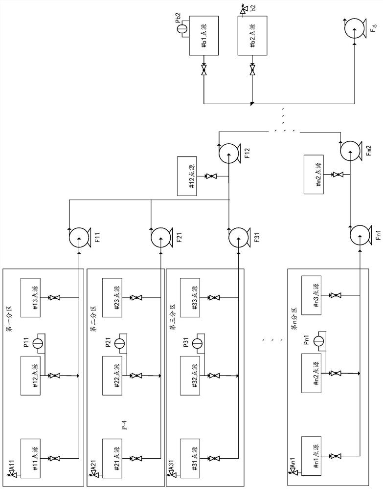
[0032] Such as figure 2 As shown, the odor collection system of the present embodiment includes a control unit and a plurality of collection pivoters, collecting the tube for odor collection of the odor point source; multiple points sources are divided into multiple regions, each area The collected pilot corresponding to the source is connected to a one-stage female tube. The first-level fan is collected at one end of the female tube, and each fan is divided into multiple groups. The first-level fan in each group passes the secondary female tube and corresponding. The secondary fan is connected, and it is subjected to a secondary, until all N-class hams are connected to the total fan; where the secondary fan to the n-level fan and the overall wind turbine are connected at least more than one independent collection branch; at least the area A first pressure detector is provided in a collection branch, and a second pressure detector is provided with at least one independent collection branch of the secondary fan or the total fan or the total fan; the control unit is based on each of the first pressure detectors and the first The pressure value of the second pressure detector is adjusted to the fans and the overall fan. The present invention detects the pressure on the collecting pipe, and controls all levels of wind turbines and turns according to the detected pressure values, thereby achieving precision collection of odor, so that the actual gas supply volume of each odor point source is designed; The above process is automated, and the control accuracy is high.
[0033] In a specific embodiment, a valve is provided on each collecting force, and each of the first pressure detecting members is mounted on a valve intake or point source structure at the maximum position in the corresponding area, and the second pressure detector is mounted. The valve intake end or point source structure at the maximum position of the overall pipe damage in each independently collecting the unit. The first pressure detecting member and the second pressure detector are micro-voltage sensors.
[0034] When the specification is specifically (i.e., the partition), the corresponding partitioning and the device are configured as follows:
[0035] In a partition (ie, the region), a partition is set to a centrifugal or Roots fan (first-class fan), and the fan safety level is one or the air-proof or anti-corrosion. At the minimum calculation of the air volume point source (the air volume is obtained by CJJ / T 243-2016 national standard), a negative pressure respiratory valve is provided, and the respiratory valve start pressure is equal to 1.2 to 2 times that of the maximum tube resistance pressure in the partition, which is not greater than the maximum static pressure of the fan inlet. . A pressure-sensor before calculating the most unfavorable point (the maximum point of the overall tube loss) is calculated in the partition, or the pressure content is -10 kPa ~ + 5 kPa.
[0036] Each partition is set one-stage female tube, of which one end of the first-stage masterpiece is connected to the first-stage fan, and the first-class fan export is connected to the superiors (secondary master tube), and one end of the superiors and higher levels Fan import or total fan is connected, and it is pushed. Each point source is collected by each point source, which is connected to the primary master tube (the first-stage master tube is connected to the upward direction, preventing the condensed water from the pipe from flowing into the female tube, causing confusion in the system, and setting adjustment Valve one, the front end of the valve, the ball valve detection port of the DN50, the adjustment valve is a butterfly valve, the ball valve or the shutter valve, and the connection method is a flange.
[0037] When the number of odor points in the system is ≤6, one partition is partitioned, and the inner point source is less than 3, and the other point sources are directly connected to the total bus tube. Unsigned point sources are configured in partition within the partition except for the fan.
[0038] When the odor point source is greater than 6, a partition source does not exceed 3 divisions. When the number of final point sources is more, the excess source is directly included in the total master tube (not more than 3), when the number of partitions When the partition is performed, the point source closest to the total fan should be removed from the partition, directly incorporating the female tube, and configuring microstatal sensors, valves and negative pressure respiratory valves, wherein the micro-pressure sensor range is the maximum static pressure of the total fan. ~ + 1kpa selection, negative pressure breathing valve is 0.8 ~ 0.95 times selection of the maximum static pressure of the fan.
[0039] When the partition exceeds three, a secondary fan should be established for collecting components that do not exceed 3 partitions, and simultaneously does not exceed 3 points. The gas is charged to the total fan.
[0040]The initial calculation of the extraction amount of each fan is performed according to the method described in CJJ / T 243-2016, and after the pre-calculation data is obtained, the structure of the liquid level increase is increased by 30% to 70% of the gas space on the basis of the predetermined data. ~ 5 times / h ventilation air volume, in the equipment, 30% to 100%, internal actual space increased by 1 to 3 times / h, and the equipment is not calculated.
[0041] In addition, all tube resistance in the system calculates the calculation by isothermal flow.
[0042] The import of the partition fan is maximized in accordance with 1 to 2 times the maximum tube loss pressure in the partition, and the exit pressure is superimposed to the tube damage segmentation of the partition to the import of the total fan (or the secondary fan). When there is another partition or point source in a partition or point source to enter the same fan, the fan export feature should be superimposed, where n is the number source number of front end partitions or separate collected points. When the partition is A, the front end has b, C, the first segment is A ~ B, only calculates the air volume of a partition; the second segment is b ~ c, the calculation of the air volume is A + B, A area Sub-control resistance = b ~ c section total pipe resistance * (a sum of the wind calibration of a partition / AB area) / n; the third paragraph is B ~ C segment, calculating the air volume is a + B + C, A distinguished pipe resistance is b ~ Class C Total Tube Resistance * (A Summary of Wind Spaces / ABC Region) / N;
[0043] The second-stage fan import pressure is superimposed and calculated according to the partition pipe and separate collection point source pipe resistance. On the basis of calculating the value, the value is selected, and the exit wind pressure is based on the dispatched outlet. Calculate logic superposition and.
[0044] Total fan import static pressure is imported according to each secondary fan to the total fan (different segmentation and different segments of the total female female tube), separate collection point source to the total wind turbine import (segmentation summation) and odor treatment system The pipe resistance is superimposed and calculated, and the value is valued in accordance with the total value of 1.1 to 2 times, and the exit wind pressure is taken on the delivery requirements.
[0045] Distribution fan air volume selection is 1.1 to 1.3 times that of all point sources of the partition and separate collection point, the secondary fan air volume selection is 1.2 to 1.5 times the partition and separate collection point sources, according to this type, The air volume of the overall fan is selected for all pre-prodaders and 1.2 to 1.5 for separate collection points.
[0046] The invention also discloses a collection method based on the odor collection system as described above, including:
[0047] Set the constant voltage interval, read interval, pressure deviation, adjustment latency and single frequency range; wherein the constant voltage value refers to a pressure interval that needs to be stabilized; the pressure offset is the first pressure detecting first pressure detection The absolute value of the highest or lowest pressure difference between the constant voltage interval; when the first pressure value is higher than the maximum pressure, the pressure deviation amplitude is the difference between the first pressure value and the highest pressure value; when the first pressure value is lower than the minimum pressure At the time, the pressure deviation is the difference between the first pressure value and the lowest pressure value; when the first pressure value is located in a constant voltage interval, the calculation is not performed; the adjustment waiting time is a single modulated system waiting time, during which Whether there is a pressure deviation amplitude, it is not adjusted;
[0048] According to the comparison of the first pressure value detected by the first pressure detecting member, the control unit obtains the pressure deviation amplitude, and then obtains the corresponding adjustment waiting time and the single frequency range depending on the pressure deviation amplitude, and finally according to the adjustment waiting time and single Sub-frequency amplitude adjustment of the first-class fan;
[0049] Setting the M-class fan with its corresponding second pressure detector, set the secondary interlock with the pressure detectors in the region of the region, where the pressure detector is the largest in the region, wherein 2 ≤ m ≤ n;
[0050] Set the total fan with its corresponding second pressure detector, which corresponds to the second pressure detector to set the secondary interlock with the N-class fan with the maximum tube resistance;
[0051] When the primary fan is adjusted according to the first pressure value of the first pressure detector, the secondary interlocking of the secondary fan is still larger than the upper limit of the constant voltage section, and the minimum pressure value corresponding to the first level chain (ie two The storm is adjusted from the detected value of the pressure detector according to its pre-stage, and the transformation is changed to the detection value of its second pressure detector, and the lowest pressure value is canceled, further increase in the actual pressure to reach the set value. ; Push it according to the class until the total fan is adjusted.
[0052] Specifically, the pressure deviation amplitude is divided into three gears according to the size. The difference between the difference is 0 to 150Pa, the difference between the two gear is 150 ~ 600Pa, and the difference between the three gear is 300 ~ 600Pa; the adjustment latency is a single modulated system. Waiting time, during which no matter whether there is pressure deviation amplitude, no adjustment. Depending on the amplitude of the pressure deviation, the adjustment latency is divided into three gears (corresponding to the pressure deviation amplitude), one gear 600 ~ 1200s, two gears 300 ~ 600s, three gears 0 ~ 300 seconds; single frequency frequency amplitude is divided into three gears (with The pressure deviation is corresponding to the magnitude of 0.2 to 1 Hz, two gears of 0.5 to 5 Hz, three gears 1 to 10Z.
[0053] When there is a secondary fan, the pressure value of the partition or point source is chain with the partition fan, and the fan frequency conversion adjustment is performed in the above manner; set the secondary fan and the micro-pressure sensor set by the separate collection point to set one level chain. The secondary interlock is set to the microstatal sensor with the largest internal pipe resistance in the partition; set the minority fan with the microstatal sensor set by the Separate Collection Source, and the separate collection point source belonging to the secondary fan associated with the maximum tube resistance The microstatal sensor sets a secondary interlock; when the partition fan (primary fan) is still greater than the upper limit of the constant voltage value after the above adjustment, the second-stage interlocking of the secondary fan is started, the minimum pressure of the first level chain Value, further increase in the above logic allows the actual pressure of the partition to reach the set value, the secondary regulation of the total fan is the same as the secondary fan.
[0054] When there is no secondary fan, it is replaced by the main fan.
[0055] The above invention is further explained in conjunction with a complete embodiment below:
[0056] Such as image 3 As shown, take a burn garbage power plant as an example, the plant has 5 stink sources, divided into # 1 ~ # 5; according to the separation distance of each source, the anaerobic water sedimentation tank, intermediate pool and dehydrated centrifuge Set to a partition, adjust pool A, adjustment pool B and grid machine and set to a separate gas supply point source.
[0057] Calculate the amount of pumping and the tube resistance is as follows:
[0058]
[0059]
[0060] Division fan air volume selection is design air volume 9400nm 3 / H 1.3 times, 13000 nm after regulation 3 / h, import static pressure According to the least disadvantaged point (# 2 source) tube damage 1709Pa 1.5-fold selection, the regularity is 2600Pa, the partition fan export pressure is 269.7Pa according to the stack pressure, according to 1.5 times selection, the rule 400Pa;
[0061] Total fan air volume selection is design air volume 17500nm 3 1.3 times of / h, 23000 nm after regulation 3 / h, imported static pressure calculated value is 1843Pa, press 1.2 times selection, 2200Pa after regulation, export is empty, press 200 Pa.
[0062] A partition is the most unfavorable point to the # 2 source, install the microstatal sensor P1 on the # 2 point source collection pipe, select the range of -2.5 ~ + 1 kPa, the accuracy is 50Pa, and install the negative pressure valve on the # 1 point source gas supply pipeline A1, set the starting pressure to -2kpa. Installing the microstatal sensor P2 on the # 5 point source collection pipe, selecting the range of -2kpa ~ + 1kpa, the accuracy is 100Pa, and the negative pressure valve A2 is installed on the # 4 point supply pipe, set the starting pressure to -2.2 kPa.
[0063] When the control is performed, the microstatal sensor P1 is chain to the partition fan F1, and the control logic is set as follows:
[0064] Set the constant voltage interval to -1.5kpa ~ -0.5kpa; reading interval 5s; pressure deviation is 50Pa, two gears are 150Pa, three gears are 300Pa; adjustment waiting time is a step 70S, two gear 35s, three File 10s; single frequency frequency range of 0.3 Hz, 2 gear 3 Hz, three gears 5 Hz.
[0065] Micro-pressure sensor P2 and total fan F 总 Chain, set the following control logic:
[0066] Set the constant voltage interval to -1.8kpa ~ -0.8kPa; read interval time 10s; pressure deviation is 50Pa, two gears 200Pa, three gears are 400Pa; adjustment latency is 140s, two gear 70s, three Fixed 10S; single frequency frequency range of 0.2 Hz, 2 germay, three gears 5 Hz.
[0067] Interlocking the microstatal sensor P1 with the total fan, setting the following control logic:
[0068] When the actual value of the microstatal sensor P1 is greater than 0.5 kPa and the partition fan F1 is full frequency operation, the original total fan chain is shielded, and the following control logic is performed:
[0069] Constant voltage settings are automatically adjusted to ≤ -0.8kPa, read interval 30s; pressure deviation amplitude is 100Pa, two gears are 150Pa, three gears are 300Pa; adjustment latency is a fixed 480S, two gear 240s, three gear 120s The single frequency range is 0.2Hz, two gears 1 Hz, three gears 2 Hz.
[0070] The above is merely preferred embodiments of the present invention, and the scope of the invention is not limited to the above embodiments, and any technical solutions under the thinking ideas of the present invention are within the scope of the present invention. It should be noted that in terms of ordinary skill in the art, there is a scope of protection of the present invention, without departing from the principles of the invention.

PUM

no PUM

Description & Claims & Application Information

We can also present the details of the Description, Claims and Application information to help users get a comprehensive understanding of the technical details of the patent, such as background art, summary of invention, brief description of drawings, description of embodiments, and other original content. On the other hand, users can also determine the specific scope of protection of the technology through the list of claims; as well as understand the changes in the life cycle of the technology with the presentation of the patent timeline. Login to view more.

Similar technology patents

Molten pool plasma radiation spectrum acquisition mechanism and laser welding device

ActiveCN106289519AAccurate collectionReliable data supportRadiation pyrometryLaser beam welding apparatusPlasma radiationLaser assisted
Owner:HUAZHONG UNIV OF SCI & TECH

Classification and recommendation of technical efficacy words

  • Accurate collection
  • High control precision

Control Method and Device For Engine

Owner:SHANDONG SHENPU TRAFFIC TECHNOLOGY CO LTD
Why Eureka
Try Eureka