Polishing device for new energy automobile manufacturing
A new energy vehicle and grinding mechanism technology, applied in the direction of grinding drive device, grinding/polishing safety device, manufacturing tools, etc., can solve the problem of inconsistent grinding degree on both sides of the brake disc, affect the braking effect of the brake disc, and make it difficult to brake the disc Problems such as the same pressure, to achieve the effect of solving the inconsistent grinding degree, speeding up the grinding efficiency, and reducing the grinding difference
- Summary
- Abstract
- Description
- Claims
- Application Information
AI Technical Summary
Problems solved by technology
Method used
Image

Examples
Embodiment 1
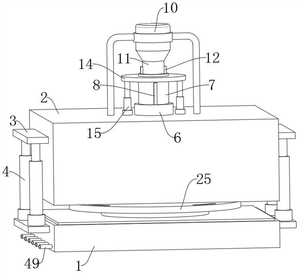
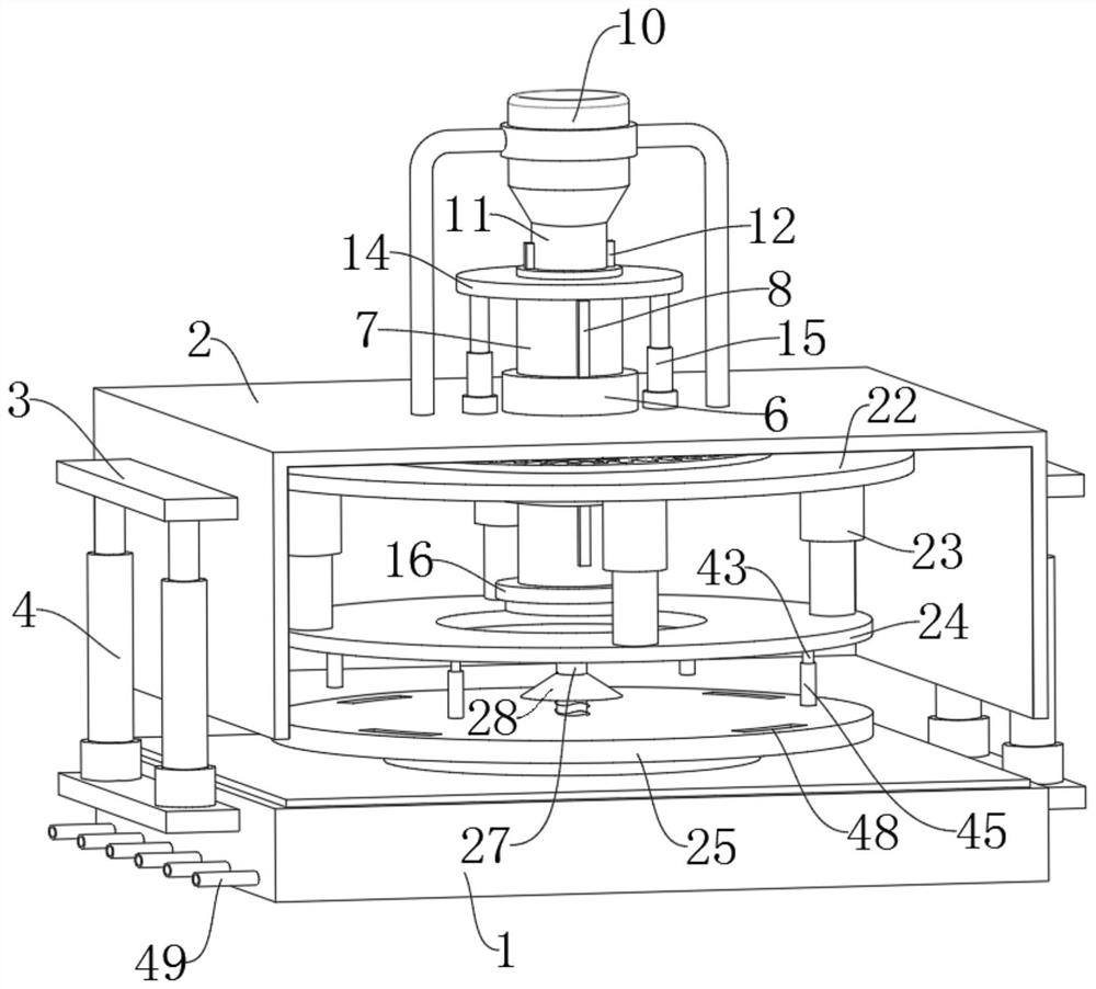
[0029] refer to Figure 1-13, a new energy vehicle manufacturing grinding device, including a base 1 and an upper shell 2, the two symmetrical outer walls of the base 1 and the upper shell 2 are fixed and welded with a connecting plate 3, the connecting plate 3 on the base 1 and the upper shell 2 A vertically arranged hydraulic telescopic rod 4 is fixedly installed between the upper connecting plates 3, and a notch 39 is provided at the edge of the top surface of the base 1, and the bottom end of the upper shell 2 can be inserted into the notch 39, and the notch 39 There are soundproof rubber strips attached to the internal fixation, and a closed cavity 5 can be formed between the base 1 and the upper shell 2. When grinding the brake disc, first control the hydraulic telescopic rod 4 to drive the upper shell 2 to move upward, and then put the brake disc into the bottom between the seat 1 and the upper shell 2, and then control the hydraulic telescopic rod 4 to drive the upper ...
Embodiment 2
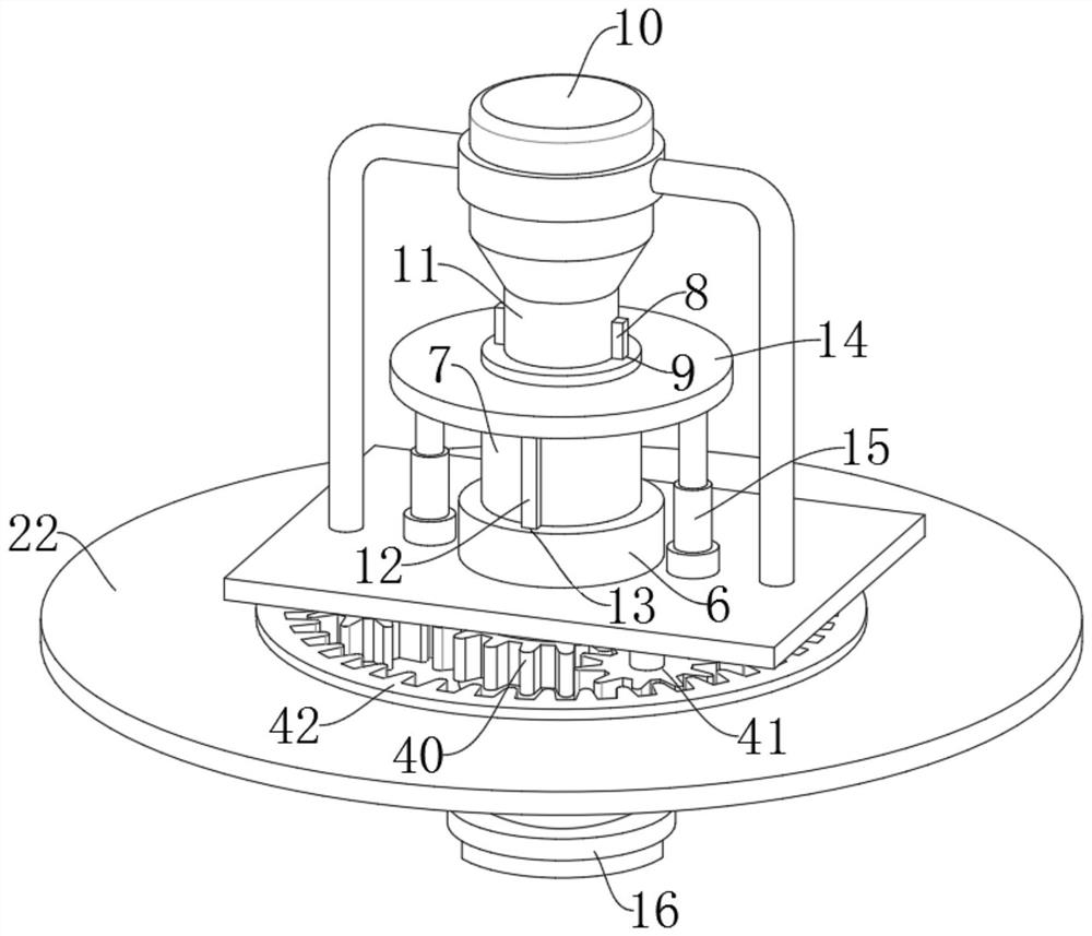
[0038] It is mentioned in Example 1 that if we control the rotation of the brake disc through a rotating shaft, the rotating shaft needs to be at the center of the brake disc, otherwise the brake disc will shake when it rotates. In Example 1, we can measure the brake disc It is placed at the center of the active grinding sheet 24 and the passive grinding sheet 25, but this method is cumbersome, and it is very unreasonable to need to measure each time the brake disc is placed. For this reason, we improve embodiment 1. Refer to figure 2 with 4 , as another preferred embodiment of the present invention, the difference from Embodiment 1 is that the center of the top surface of the passive grinding sheet 25 is fixedly provided with a center alignment mechanism, and the center alignment mechanism includes a smooth surface fixedly welded on the center of the top surface of the passive grinding sheet 25. Rod 27, the outer wall of smooth rod 27 is slidably provided with round table 28...
Embodiment 3
[0040] In Example 1, we only grind the two sides of the brake disc, but when grinding the two sides of the brake disc, there will be sticky debris at the edge of the brake disc. When taking the brake disc, these debris will melt on the edge of the brake disc, which not only affects the aesthetics of the brake disc, but also affects the performance of the brake disc. For this reason, we further improve the embodiment 1, refer to Figure 5 , as another preferred embodiment of the present invention, the difference from Embodiment 1 is that an edge grinding mechanism is provided on the opposite side walls of the active grinding sheet 24 and the passive grinding sheet 25, and the edge grinding mechanism includes 24 and the strip groove 30 at the edge of the passive polishing sheet 25, the extension line of the strip groove 30 passes through the center of the active polishing sheet 24 and the passive polishing sheet 25, and the inside of the strip groove 30 is slidably provided with ...
PUM
 Abstract
Description
Claims
Application Information
 - R&D
- Intellectual Property
- Life Sciences
- Materials
- Tech Scout
- Unparalleled Data Quality
- Higher Quality Content
- 60% Fewer Hallucinations
Browse by: Latest US Patents, China's latest patents, Technical Efficacy Thesaurus, Application Domain, Technology Topic, Popular Technical Reports.
© 2025 PatSnap. All rights reserved.Legal|Privacy policy|Modern Slavery Act Transparency Statement|Sitemap|About US| Contact US: help@patsnap.com