Plastic processing device for plastic production and processing
A processing device and plastic technology, which is applied in the field of plastic processing devices for plastic production and processing, can solve the problems of reduced precision, inability to drill holes, easy deviation of drill bits, etc., and achieve the effect of reducing shaking
- Summary
- Abstract
- Description
- Claims
- Application Information
AI Technical Summary
Problems solved by technology
Method used
Image

Examples
Embodiment 1
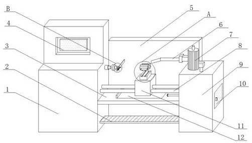
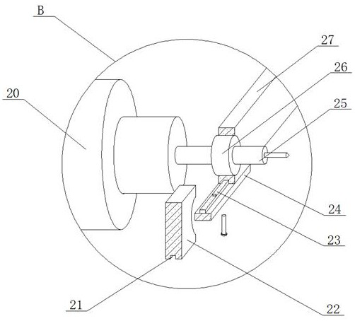
[0029] see Figure 1-Figure 6 , the present invention provides a kind of plastic processing device that is used for plastic production and processing, comprises console 1, and the right side of console 1 is provided with box body 9, and the top surface of box body 9 is fixedly installed with air pump 7, and console 1 The inside is provided with a first cavity, the right end of the first cavity is welded with a motor 36, the output end of the motor 36 is movably connected with a first rotating shaft 37, and the outer wall of the right end of the first rotating shaft 37 is provided with a first screw thread, the first rotating shaft 37 The right side is provided with the second rotating shaft 20, and the left end of the second rotating shaft 20 is movably connected with a fixed sleeve 38, and the inner wall of the fixed sleeve 38 is provided with a second thread, and the right end of the first rotating shaft 37 is screwed with the fixed sleeve 38, and the second rotating shaft T...
Embodiment 2
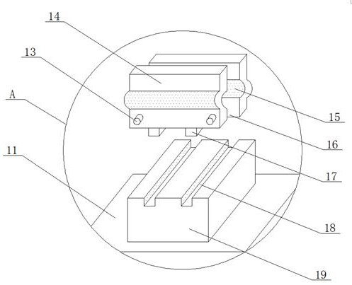
[0032] Two limit rods 8 are movably connected between the console 1 and the box body 9, and the middle parts of the two limit rods 8 are movably connected with a movable block 11, and the top surface of the movable block 11 is welded with a mounting seat 19, and the mounting seat 19 The top surface is provided with two second slide grooves 18, and the top of the mounting seat 19 is provided with a first clamping plate 14 and a second clamping plate 16, and the bottom ends of the first clamping plate 14 and the second clamping plate 16 are both Two sliders 17 are welded, and the two sliders 17 are slidably connected with the corresponding second slide grooves 18. The middle parts of the first clamping plate 14 and the second clamping plate 16 are provided with grooves 15, and the two grooves The grooves 15 correspond to each other, and the front end surfaces of the first clamping plate 14 and the second clamping plate 16 are respectively provided with a first threaded hole and a...
PUM
 Abstract
Description
Claims
Application Information