Automatic loading system

An automatic and driving device technology, which is applied in the loading field of the logistics industry, can solve the problems of large space, collapsed loading height, and large activity space requirements, and achieve simple arrangement control logic, reduce space requirements, and reduce waiting time. Effect

Active Publication Date: 2021-03-30
苏州澳昆智能机器人技术有限公司
View PDF6 Cites 8 Cited by
  • Summary
  • Abstract
  • Description
  • Claims
  • Application Information

AI Technical Summary

Problems solved by technology

However, manual loading takes a long time and labor intensity is high, resulting in long waiting time and slow turnover of vehicles, difficult and unstable recruitment of loading workers, and high cost of manual loading
[0003] In the prior art, the loading is mainly divided into three categories: one is semi-automatic loading, which transports the unstacked goods to the compartment through the transportation line, and completes the last step of packing manually. The car process relies on labor, high cost and low loading efficiency
The second type is to use the method of high-level blanking to realize automatic loading. Although this type of method gets rid of the dependence on manual work, the blanking position is set above the carriage by the gantry method, and the system requires a large space. The way of material is easy to damage the product, and it can only be applied to certain types of products and models, and the way of blanking may easily lead to inaccurate placement, and the risk of collapse may occur when the loading height exceeds the threshold
The third category is to use the manipulator to grab the goods on the transmission line and place them in the compartment. The rules of this type of placement mainly rely on the control system of the manipulator. The cost of using the manipulator is high, and the activity space needs to be large. The cost is high, the control logic and structure are complicated, and only a few commodities can be grabbed and placed at a time, and the loading efficiency is not high

Method used


Image

  • Automatic loading system
  • Automatic loading system
  • Automatic loading system

Examples


Embodiment Construction

[0034] In order to make the purpose, technical solutions and advantages of the embodiments of the present invention more clear, various implementation modes of the present invention will be described in detail below in conjunction with the accompanying drawings. However, those of ordinary skill in the art can understand that, in each implementation manner of the present invention, many technical details are provided for readers to better understand the present application. However, even without these technical details and various changes and modifications based on the following implementation modes, the technical solution claimed in this application can also be realized. The division of the following embodiments is for the convenience of description, and should not constitute any limitation to the specific implementation of the present invention, and the various embodiments can be combined and referred to each other on the premise of no contradiction.

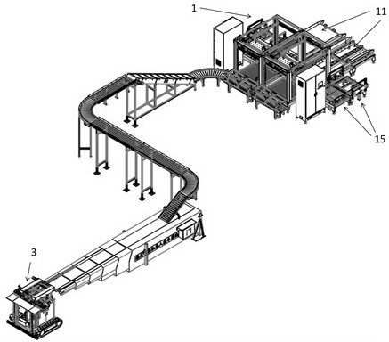
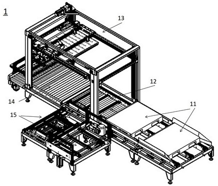
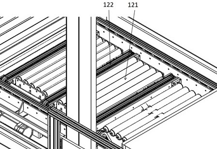
[0035] Refer below Fig...


PUM


Abstract

The embodiment of the invention relates to the field of logistics industry truck loading, and discloses an automatic loading system. The automatic loading system comprises a tray disassembling devicefor disassembling products, a conveying belt for receiving the products output by the tray disassembling device and conveying the products, and a loading part for receiving, arranging and placing theproducts. The loading part comprises an accelerating unit, an integrating unit connected with the accelerating unit, and a placing unit. According to the automatic loading system, full-automatic loading can be achieved, dependence on manpower is avoided, the occupied space of the system is reduced, the safety of products is guaranteed, the automatic loading system can adapt to vehicle bodies of different sizes, the applicability of the system is improved, the cost of the system is reduced, and the loading efficiency is improved.

Description

technical field [0001] The embodiment of the present invention relates to the field of vehicle loading in the logistics industry, in particular to an automatic loading system. Background technique [0002] With the mass sales of fast-moving consumer goods such as milk, beverages, and alcohol, pressure has been placed on the trucking and transportation industry. Fast-moving consumer goods such as milk are stored in the form of pallets after they are produced. They are usually carried by pallets. Enter the transportation link after the car. However, manual loading takes a long time and is labor-intensive, which leads to long waiting time and slow turnover of vehicles. It is difficult and unstable for loading workers to recruit workers, and the cost of manual loading is high. [0003] In the prior art, the loading is mainly divided into three categories: one is semi-automatic loading, which transports the unstacked goods to the compartment through the transportation line, and...

Claims


Application Information

Patent Timeline
Patent Type & Authority Applications(China)
IPC IPC(8): B65G67/04B65G67/08B65G13/07B65G47/29B65G47/31B65G47/26B65B69/00
CPCB65B69/00B65G13/07B65G47/26B65G47/29B65G47/31B65G67/04B65G67/08
Inventor 李政德刘霞武杰戴冬冬霍英杰
Owner 苏州澳昆智能机器人技术有限公司
Why Eureka
Try Eureka