
Leveling frame structure and installation method thereof

A frame structure and frame technology, applied in the field of leveling frame structure and its installation, can solve the problems of limited metal keel strength and nail holding force, warping deformation, large space occupation of leveling base, etc., to achieve convenient and fast installation and disassembly, The effect of enhanced section moment of inertia and avoiding quality problems

Pending Publication Date: 2021-03-30
ZHEJIANG YASHA DECORATION
View PDF1 Cites 0 Cited by
  • Summary
  • Abstract
  • Description
  • Claims
  • Application Information

AI Technical Summary

Problems solved by technology

[0003] Chinese patent [CN201710246897.X] discloses a wall leveling system and leveling method, which solves the problem that the existing wall light steel keel leveling method has a complicated installation structure, and the leveling base takes up a lot of space, which is not suitable for small spaces.
[0005] 1. The stud needs to be rotated during operation, which is not convenient enough to operate;
[0006] 2. The light steel keel used in this leveling system is the traditional light steel keel, which has low strength and poor nail holding power. During use, the decorative material is prone to deformation due to the influence of temperature and humidity, which leads to failure of the threaded connection. Arching or warping deformation, eventually causing the veneer to loosen;
[0007] 3. Due to the limited strength of the metal keel and nail-holding force, the wall leveling system cannot meet the installation of tile / stone dry-hanging technology, and the scope of use is limited, so it cannot be used for the installation of heavy decorative panels

Method used


Image

  • Leveling frame structure and installation method thereof
  • Leveling frame structure and installation method thereof
  • Leveling frame structure and installation method thereof

Examples


Embodiment Construction

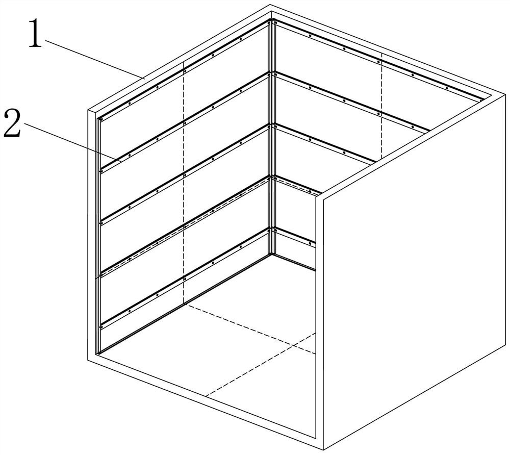
[0041] In order to more clearly illustrate the embodiments of the present invention and the technical solutions in the prior art, the specific implementation manners of the present invention will be described below with reference to the accompanying drawings. Obviously, the accompanying drawings in the following description are only some embodiments of the present invention, and those skilled in the art can obtain other accompanying drawings based on these drawings and obtain other implementations. In addition, the belonging of the design orientation only indicates the relative positional relationship between the components, not the absolute positional relationship.

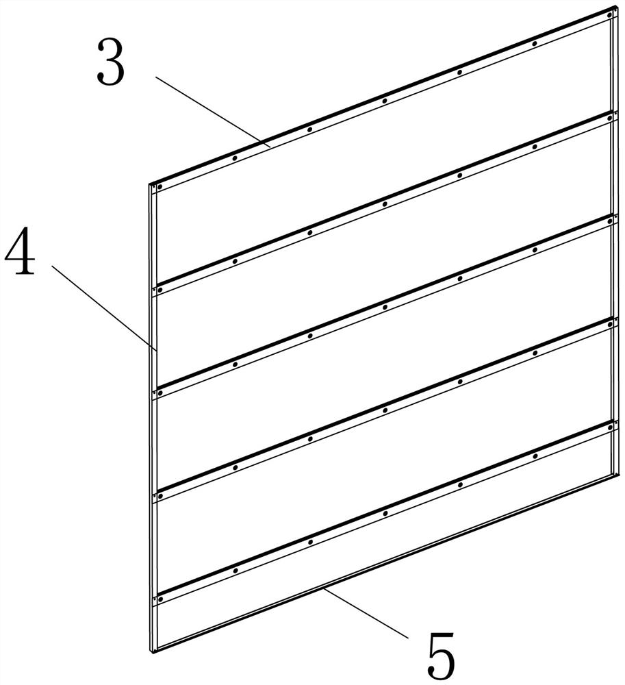
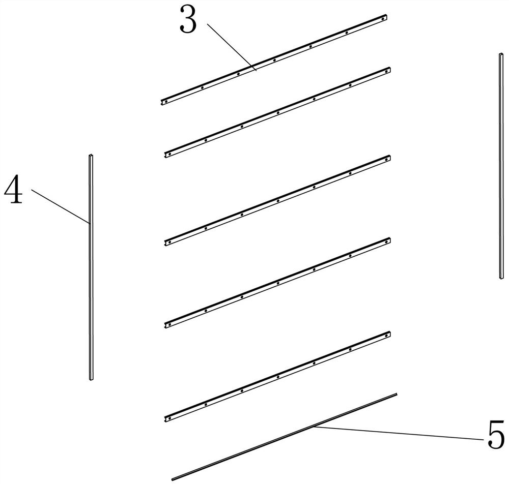
[0042] see figure 1 , figure 2 , image 3 , in the embodiment of the present invention, on the one hand, the present invention provides a leveling frame structure, including the original wall surface 1, characterized in that it also includes a leveling keel frame 2 for laying on the original wall surface 1, Th...


PUM


Abstract

The invention discloses a leveling frame structure and an installation method thereof. The leveling frame structure specifically comprises an original wall surface and further comprises a leveling keel frame used for being laid on the original wall surface, wherein the leveling keel frame comprises horizontally-arranged transverse strips, vertically-arranged U-shaped keels and L-shaped angle steelarranged at the bottom of the original wall surface; the two ends of each transverse strip are embedded into the two corresponding U-shaped keels to form the frame structure; and when the leveling keel frame is vertically laid on the original wall surface, the spacing distances between every two adjacent transverse strips are equal, the two ends of the uppermost transverse strip are fixedly connected with the top ends of the two corresponding U-shaped keels correspondingly, and the bottom ends of the two corresponding U-shaped keels are fixedly connected with the two ends of the angle steel correspondingly. According to the leveling frame structure, the L-shaped angle steel, the U-shaped keels, metal keels, supporting bases and wood-plastic insertion strips can be assembled and produced in batches in a factory, efficiency is high, and the leveling frame structure can be applied to various different occasions.

Description

technical field [0001] The invention relates to the field of industrial assembly decoration, in particular to a leveling frame structure and an installation method thereof. Background technique [0002] Decorating interior and exterior walls with ceramic tiles is a common practice in the field of decoration. The method of traditional tiles on the wall is mainly the wet paste method, which is installed by applying glue on the base of the wall. The construction process of this method is relatively complicated, the construction period is long and the pollution is large. And in the installation process, the tiles cannot be adjusted and replaced well, and the installation quality is not ideal. The prior art has improved it, the main ways are as follows: [0003] Chinese patent [CN201710246897.X] discloses a wall leveling system and leveling method, which solves the problem that the existing wall light steel keel leveling method has a complicated installation structure, and the ...

Claims


Application Information

Patent Timeline
IPC IPC(8): E04F13/22E04F13/23
CPCE04F13/0803E04F13/0805E04F13/0807
Inventor 丁欣欣丁泽成王文广周东珊余文钊武鹏
Owner ZHEJIANG YASHA DECORATION
Learn More