
Double-wheel pump

A technology of sheave wheel and vane wheel, which is used in the field of fluid extraction (pump) or equipment that outputs power with pressurized fluid, which can solve the problems of large mechanical loss, low efficiency and high energy consumption.

Pending Publication Date: 2021-03-30
李光惠
View PDF3 Cites 0 Cited by
  • Summary
  • Abstract
  • Description
  • Claims
  • Application Information

AI Technical Summary

Problems solved by technology

[0002] The existing water pumps are mainly centrifugal and axial flow, and the water inlet and outlet of the pump are through-type. Except for the submersible pump, the water pump needs to be filled with water when it is started at a liquid level higher than the water; the general water pump has The disadvantages of low efficiency and high energy consumption, while high-efficiency energy-saving pumps have the problems of complex structure and high cost
[0003] Existing hydraulic motors, oil pumps and other volumetric equipment, either have large mechanical losses such as vane motors, or have small flow ratios and power ratios such as gear pumps

Method used


Image

  • Double-wheel pump
  • Double-wheel pump
  • Double-wheel pump

Examples


Embodiment 1

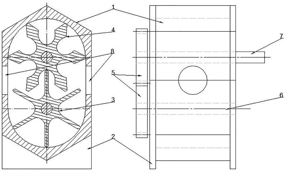
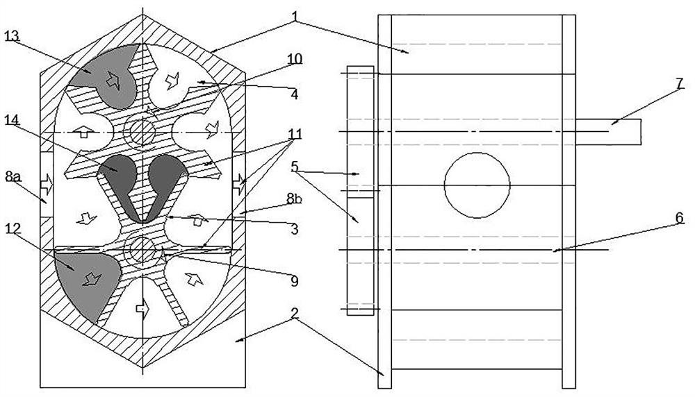
[0023] like figure 1 As shown, this embodiment shows a double-wheel pump using a pair of gears with the same size as the transmission mechanism. The cylinder body 1 adopts a cylinder body structure composed of two circular arc segments whose cross-sectional shape is the inner wall transitioning with a tangent line. It is mainly composed of a cylinder Body 1, two cylinder heads 2, a vane wheel 3, a sheave 4, a gear transmission mechanism 5, a vane wheel shaft 6, a sheave shaft 7 and the like.

[0024] as attached figure 1 , figure 2 As shown, the cylinder body 1 is a structure whose inner wall section is formed by two arc sections transitioned by a tangent line or an arc line. 1 The centers of the two arcs are set eccentrically; the rotation centers of the vane wheel 3 and the rotating shaft 6, the sheave 4 and the rotating shaft 7 are respectively concentric with the arc centers of the two arcs of the cylinder body 1; the cylinder body 1 has a fluid inlet 8a and an outlet 8...

Embodiment 2

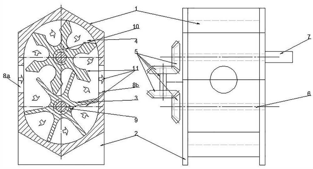
[0029] This embodiment is a power device powered by pressurized liquid, as attached image 3 As shown, the equipment configuration of this embodiment is consistent with that of Embodiment 1, and the difference from Embodiment 1 is that the synchronous transmission mechanism 5 adopts the structure of a bevel gear plus a transmission shaft, and the rotating shaft 7 is a power output shaft.

[0030] The working principle of this embodiment:

[0031] Pressurized liquid is input at the entrance of the equipment; on the side of the inlet 8a, the outer edge of the vane wheel 3 moves to contact the inner wall of the cylinder body 1, and to the vane on the side of the vane wheel 3 outlet 8b, the vane wheel 3 generates a positive torque; and the groove of the groove wheel 4 The blades of the blade wheel 3 in contact generate a reverse torque; the two torques are equal in magnitude and opposite in direction, and the blade wheel 3 is in a balanced state. The outer edge of the vane 4 of t...


PUM


Abstract

The invention discloses a double-wheel pump which comprises a cylinder body (1), a cylinder cover (2), a vane wheel (3), a grooved wheel (4) and a transmission mechanism (5). The vane wheel (3) and the grooved wheel (4) keep synchronous coupling rotation in the cylinder body under the action of the synchronous transmission mechanism (5), and the rotation directions are opposite. The double-wheel pump is a positive displacement pump, so that compared with a gear pump, the displacement of the pump can be greatly improved, the efficiency of the pump is improved, and the problem that the pump is used for lubricating equipment of fluid except oil is solved.

Description

technical field [0001] The invention relates to technical fields such as water pumps, oil pumps, hydraulic motors, etc., in particular, it is a device used in fluid pumping (pump) or outputting power with pressurized fluid. Background technique [0002] Existing water pumps are mainly centrifugal and axial flow, and the water inlet and outlet of the pump are through-type. Except for submersible pumps, water pumps need to be filled with water when starting at a liquid level higher than water; general water pumps have The disadvantages of low efficiency and high energy consumption, while high-efficiency energy-saving pumps have the problems of complex structure and high cost. [0003] Existing hydraulic motors, oil pumps and other positive displacement equipment either have large mechanical losses such as vane motors, or have small flow ratios and power ratios such as gear pumps. Contents of the invention [0004] The purpose of the present invention is to design a double-w...

Claims


Application Information

Patent Timeline
Patent Type & Authority Applications(China)
IPC IPC(8): F04C2/20F04C15/00
CPCF04C2/20F04C2/084
Inventor 李光惠
Owner 李光惠
Learn More