Quick insertion locking joint

A fast technology for locking joints, which is applied in the direction of pipes/pipe joints/fittings, packing seals with fluid pressure, passing components, etc. It can solve problems such as complex structures, large handles occupying space, and time-consuming and labor-intensive quick joints.

Pending Publication Date: 2021-03-30
高安市璐克斯机械有限公司
View PDF0 Cites 2 Cited by
  • Summary
  • Abstract
  • Description
  • Claims
  • Application Information

AI Technical Summary

Problems solved by technology

In existing quick connectors, such as Figure 9 As shown, it generally includes a main body 25, a handle 26 and a pin 27. By rotating the handle, the arc-shaped protrusion at one end of the handle is snapped into the arc-shaped groove of the male head to realize the sealed connection of the j...

Method used


Image

  • Quick insertion locking joint
  • Quick insertion locking joint
  • Quick insertion locking joint

Examples


Embodiment 1

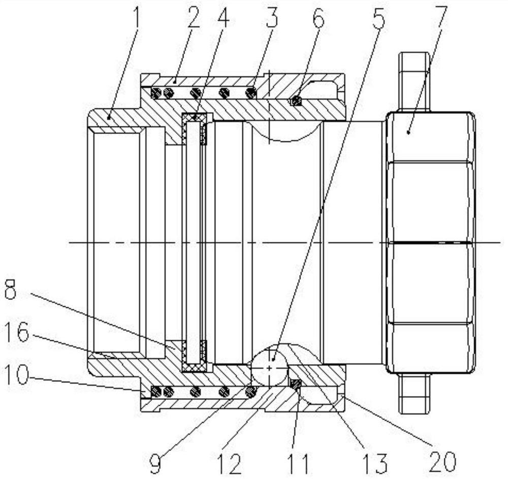
[0030] Such as figure 1 As shown, this embodiment provides a quick insertion locking joint, including a female body 1, a sliding sleeve 2, an elastic element 3, a sealing ring 4, a limiting element 5 and a retaining ring 6, and one end of the female body 1 is provided with a plug Interface, the socket is used to connect the Camlock male connector 7, the inner wall of the socket is provided with a sealing seat 8, the sealing ring 4 is arranged on the side of the sealing seat 8 close to the port of the socket, and the side wall of the socket is provided with a plurality of limit holes 9 Each limit hole 9 is provided with a limit element 5 and the limit hole 9 can limit the limit element 5 to break away from the limit hole 9 inwardly, and the outer wall of the female head body 1 is provided with a first boss 10, The sliding sleeve 2 is sleeved outside the first boss 10, and the outer wall of the female head body 1 is provided with a card slot 11, and the card slot 11 is arranged...

Embodiment 2

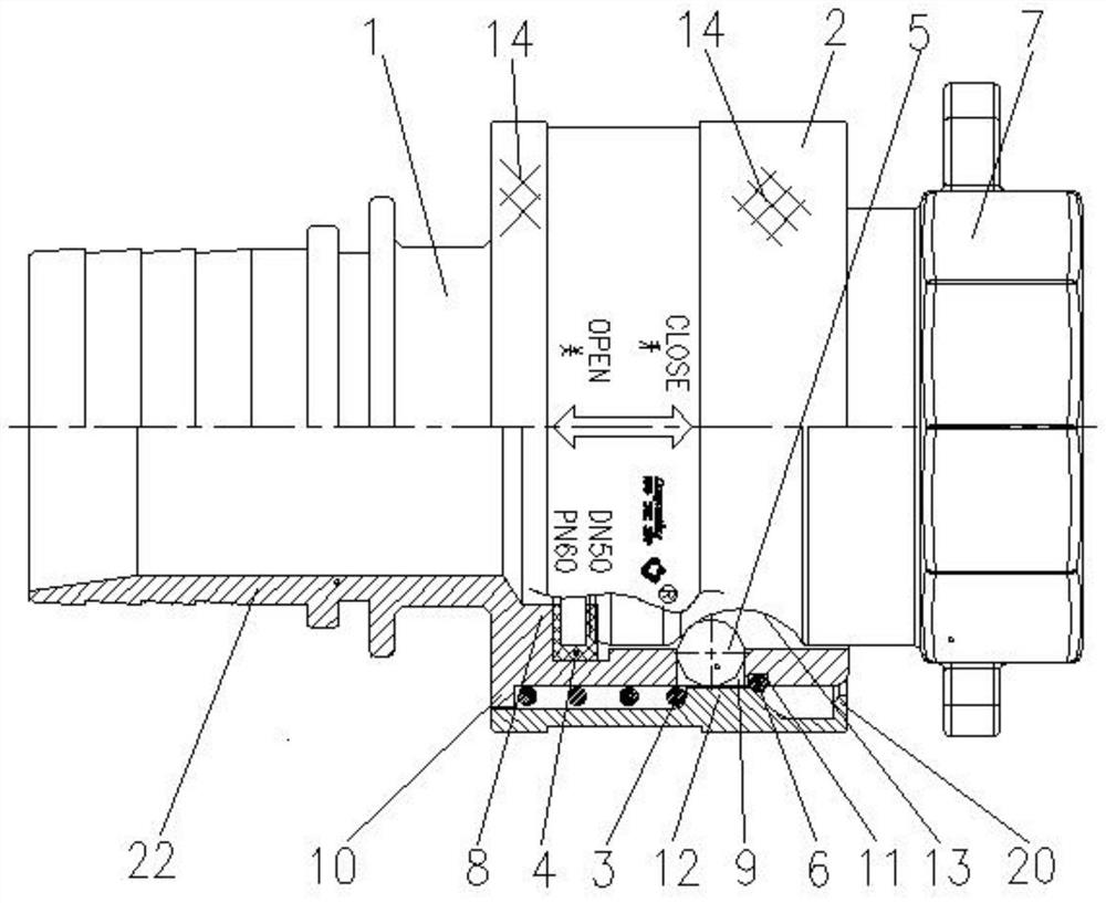
[0038] Such as figure 2 As shown, this embodiment provides a quick-insert locking joint, which is different from the quick-inserting locking joint in Embodiment 1 in that the outer surface of the sliding sleeve 2 is provided with anti-slip mesh protrusions 14, which can increase the sliding The frictional force between the cover 2 and the hand facilitates pushing the sliding cover 2.

[0039] Wherein, the connection port for connecting with the pipe fitting is set as a tail pipe 22, through which the tail pipe 22 is connected with the pipe fitting.

Embodiment 3

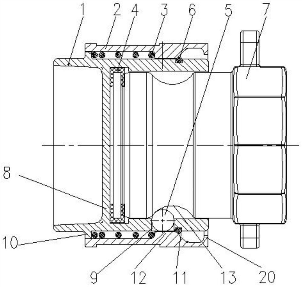
[0041] Such as image 3 As shown, in the quick insertion locking joint provided in this embodiment, the sealing seat 8 is a sealing partition, and the sealing partition seals the end of the female head body away from the socket, and the sealing ring 4 is arranged on the sealing partition close to the port of the socket. On one side, through the setting of the sealing partition, the pipe fittings can be sealed and dust can be prevented from entering.


PUM


Abstract

The invention discloses a quick insertion locking joint. One end of a female joint body is provided with an insertion port, the inner wall of the insertion port is provided with a sealing base, a sealing ring is arranged on the sealing base, the side wall of the insertion port is provided with a plurality of limiting holes, each limiting hole is internally provided with a limiting element, the outer side wall of the female joint body is provided with a first boss, a sliding sleeve is arranged outside the first boss in a sleeving mode, a clamping groove is formed in the outer side wall of the female joint body, a check ring is arranged in the clamping groove, a second boss is arranged on the inner wall of the sliding sleeve, the female joint body is sleeved with an elastic element, the elastic element is arranged between the second boss and the first boss, a limiting groove is formed in the outer wall of a Camlock male joint in the circumferential direction, when the Camlock male jointis inserted into the insertion port, the second boss enables the limiting elements to be fixed in the limiting groove and enables the Camlock male joint to press the sealing ring on the sealing base,and when the second boss slides away from the limiting holes, the limiting elements can be disengaged from the limiting groove. The quick insertion locking joint is simple in structure, small in occupied space, convenient and fast to disassemble and assemble and good in sealing performance.

Description

technical field [0001] The invention relates to the technical field of pipe joints, in particular to a quick insertion locking joint. Background technique [0002] Quick connectors include hydraulic quick connectors and various fluid quick connectors. It is a connection device that quickly connects or disconnects pipelines and realizes quick disassembly. It is widely used in petroleum, metallurgy, hydropower, construction machinery, ships, electromechanical equipment and other fields. The connection structure of the quick connector is the most important part of the quick connector. Its connection method and structure directly determine the convenience, reliability and product quality of the quick connector. In existing quick connectors, such as Figure 9 As shown, it generally includes a main body 25, a handle 26 and a pin 27. By rotating the handle, the arc-shaped protrusion at one end of the handle is snapped into the arc-shaped groove of the male head to realize the seal...

Claims


Application Information

Patent Timeline
IPC IPC(8): F16L37/22F16L37/23
CPCF16L37/22F16L37/23F16L17/073F16L37/08
Inventor 卢晓斌杨成勇
Owner 高安市璐克斯机械有限公司
Why Eureka
Try Eureka