Straightness calibration device for V-shaped conveying roller way and using method thereof

A technology for calibrating device and conveying roller table, applied in the direction of roller table, measuring device, transportation and packaging, etc., can solve the problem that the horizontality and verticality of the V-shaped roller shaft cannot be guaranteed, and the smooth transportation and straightness of round bars of various specifications cannot be guaranteed. In order to achieve the effect of good promotion and application value, reducing the frequency of roller table calibration and manpower time investment, and improving the effective operation rate of equipment

Active Publication Date: 2021-03-30
BAOSTEEL SPECIAL STEEL SHAOGUAN CO LTD
View PDF15 Cites 2 Cited by
  • Summary
  • Abstract
  • Description
  • Claims
  • Application Information

AI Technical Summary

Problems solved by technology

This technology can think that the center of the V-shaped roller is on a straight line within the error of ±0.5mm, but the error is still relatively large, and the underlying fundamental problem is that the levelness of the rotating shaft of each V-shaped roller and the alignment with the conveying direction cannot be guaranteed. Verticality, etc., cannot ensure that round bars of various specifications are conveyed smoothly on the conveying roller table
That is to say, the calibration accuracy of the straightness of the V-shaped roller conveying roller table in the prior art needs to be improved.

Method used


Image

  • Straightness calibration device for V-shaped conveying roller way and using method thereof
  • Straightness calibration device for V-shaped conveying roller way and using method thereof

Examples


Embodiment Construction

[0031] The present invention will be described in detail below in conjunction with the accompanying drawings and embodiments.

[0032] It is worth noting that the orientation words such as "up" and "down" involved in this article are all determined relative to the perspective of the drawings, and are only for the convenience of description, and cannot be understood as limitations on the technical solution.

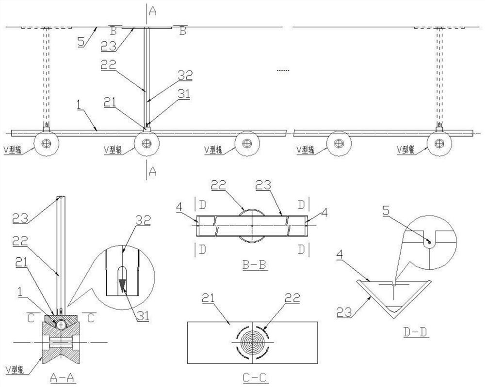
[0033] Such as figure 1 As shown, the present invention provides a V-shaped conveying roller flatness calibration device, which includes a standard sample tube 1, a standard frame, a hanger, a V-shaped piece and a wire 5 for a stay.

[0034]The standard frame comprises two vertical bases 21, standpipes 22 and longitudinal bars 23, the bottom of the standpipe 22 is vertically connected with the base 21, the bottom of the standpipe 22 is provided with a plurality of observation holes, the top of the standpipe 22 is connected to the vertical The rods 23 are vertically connec...


PUM


Abstract

The invention relates to a straightness calibration device for a V-shaped conveying roller way. The straightness calibration device comprises a standard sample pipe, a standard frame, a hanger, a V-shaped piece and a stay wire steel wire. The standard frame comprises bases, vertical pipes and longitudinal rods, the bases are perpendicular in pairs, the bottom ends of the vertical pipes are perpendicularly connected with the bases, a plurality of observation holes are formed in the bottom ends of the vertical pipes, the top ends of the vertical pipes are perpendicularly connected with the longitudinal rods, the bottoms of the bases are conical surfaces matched with the conical surfaces of the V-shaped rollers, and inverted first U-shaped grooves are formed in the middles of the bottoms of the bases. Cross-shaped scales are arranged on the top surface of the base. The hanger is arranged in the vertical pipe and comprises a hanging cone and a hanging wire, the hanging cone is connected with a longitudinal rod located at the top end of the vertical pipe through the hanging wire, V-shaped pieces are arranged at the two ends of the longitudinal rod respectively, second U-shaped grooves are formed in the tops of the V-shaped pieces, and the connecting line of the groove bottom circle centers of the second U-shaped grooves of the V-shaped pieces at the two ends is parallel to the longitudinal rod. Straightness calibration is carried out on the conveying roller way composed of the multiple V-shaped rollers, and compared with the prior art, the calibration precision is improved.

Description

technical field [0001] The invention relates to the technical field of round bar flaw detection equipment, more specifically, it relates to a V-shaped conveying roller table flatness calibration device and its application method. Background technique [0002] The through-type automatic ultrasonic testing of round rods is a common round rod flaw detection technology. It is made by making the round rods advance through the flaw detection equipment on the conveying equipment, and at the same time, the ultrasonic probe in the ultrasonic flaw detection equipment rotates around the round rods to form ultrasonic waves. The spiral scanning of the round bar by the probe, the coupling water is filled between the probe and the round bar, the ultrasonic wave emitted by the probe enters the round bar through the coupling water, and then the echo data is detected to detect whether there are any unacceptable defects inside the round bar. That is to say, the automatic technology must be ins...

Claims


Application Information

Patent Timeline
Patent Type & Authority Applications(China)
IPC IPC(8): G01B5/252B65G13/00
CPCG01B5/252B65G13/00
Inventor 胡柏上刘栋麻国晓张浩高伟石秋生莫杰辉王峰麦海源
Owner BAOSTEEL SPECIAL STEEL SHAOGUAN CO LTD
Why Eureka
Try Eureka