Optical target simulation system based on LED display screen

An LED display and target simulation technology, applied in the field of optical target simulation system, can solve the problems of being vulnerable to damage, fixed target pattern form, and strict ambient lighting requirements, and achieve the effect of rapid change

Inactive Publication Date: 2021-03-30
NANJING UNIV OF SCI & TECH
View PDF5 Cites 0 Cited by
  • Summary
  • Abstract
  • Description
  • Claims
  • Application Information

AI Technical Summary

Problems solved by technology

[0003] The traditional USAF1951 resolution target is a lithography target, which is made of transparent quartz glass as the substrate, and the surface is coated with an opaque chrome layer outside the pattern, so it is easily damaged during transportation and loading and unloading, resulting in loss of precision; and The pattern of the produced target is fixed, the observation angle is single, and it cannot be dynamically displayed
The large-screen projection scheme adopted abroad is to project visible light images on a large screen. Although this method is technically relatively simple, it needs to occupy a large space and has strict requirements on the surrounding environment lighting, so it is only suitable for laboratory environments. work, it is not possible to conduct outdoor field tests on large optoelectronic test systems

Method used


Image

  • Optical target simulation system based on LED display screen
  • Optical target simulation system based on LED display screen

Examples


Embodiment Construction

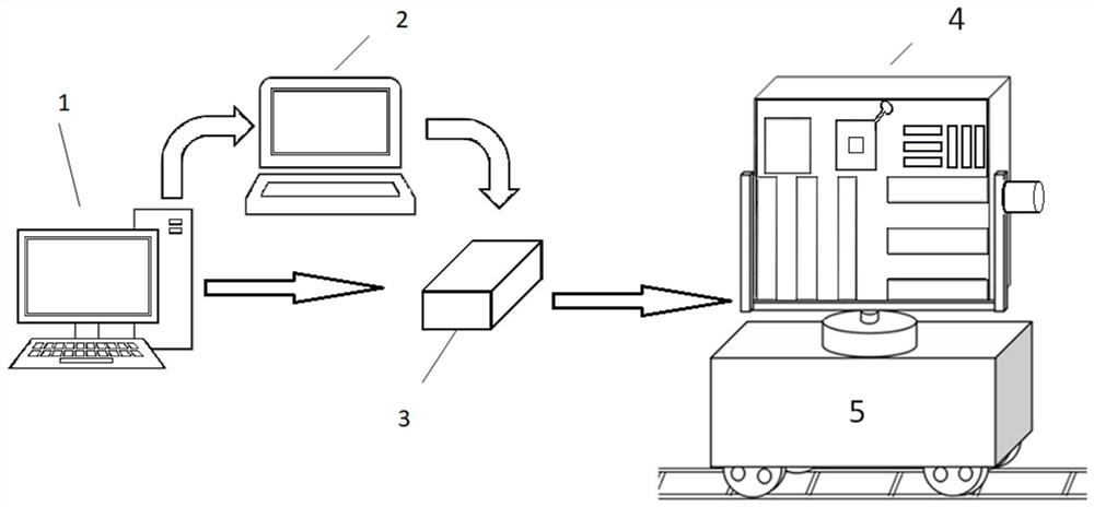
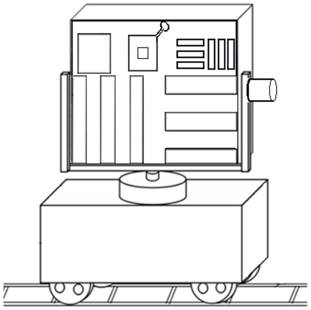
[0022] Such as figure 1 with figure 2 As shown, the present invention proposes an optical target simulation system of an LED display screen, the computer control system 1, the on-site control system 2, the image or video display control device 3 and the LED display screen 4 are sequentially connected to the optical target simulation system; The optical target simulation system also includes a moving device 5; the moving device includes a moving car, a support seat, a guide rail, a first motor, a pitch rotating shaft, a horizontal rotating shaft, a second motor and a third motor.

[0023] The LED display screen 4 is arranged at the use site.

[0024] The computer control system 1 is used to simulate the size of the display screen according to the 4-pixel resolution of the LED display screen, and to obtain the first display content of the LED display screen according to the USAF1951 target pattern or the real-scene target image, and to display the obtained first display The c...


PUM


Abstract

The invention discloses an optical target simulation system based on an LED display screen. The optical target simulation system comprises a computer control system, a field control system, an image or video display control device and the LED display screen which are connected in sequence. According to the invention, the size of the display screen can be simulated according to the pixel resolutionof the LED display screen, first display content of the LED display screen is made according to a USAF1951 target surface pattern or a live-action target image, and the made first display content issent to the image or video display control device through the field control system, so that the display content can be changed conveniently and quickly, dynamic display and brightness adjustment of asimulation target can be carried out, and the problems that traditional target paper needs to be replaced frequently and adjusted repeatedly, and the content is single are solved. In addition, the LEDdisplay screen is fixed on a motion device mechanism, so that free rotation in the horizontal and pitching directions and translation on a guide rail are realized, and multi-azimuth and multi-angle observation is achieved.

Description

technical field [0001] The invention belongs to the technical field of photoelectric measurement, in particular to an optical target simulation system based on an LED display screen. Background technique [0002] In the field test site, the optical target simulation system is often used to generate targets such as traditional USAF1951 resolution targets, people or aircraft to complete the dynamic and static performance tests of military optoelectronic systems, and provide objective and accurate test and evaluation methods for military optoelectronic systems. The design, development, and debugging of military photoelectric systems provide sufficient original data support and verification. [0003] The traditional USAF1951 resolution target is a photolithography target, which uses transparent quartz glass as the substrate, and the surface is coated with an opaque chromium layer outside the pattern, so it is easily damaged during transportation and loading and unloading, which ...

Claims


Application Information

Patent Timeline
Patent Type & Authority Applications(China)
IPC IPC(8): G09F9/33G09G3/32F16M11/08F16M11/10F16M11/12F16M11/18F16M11/42
CPCG09F9/33G09G3/32F16M11/425F16M11/121F16M11/08F16M11/10F16M11/18
Inventor 富容国宁传旺
Owner NANJING UNIV OF SCI & TECH
Why Eureka
Try Eureka