
Robotic system for surface treatment of vehicles

A technology for surface treatment and vehicles, which is applied in the field of robotic systems for surface treatment of vehicles, which can solve problems such as difficult removal of paint and achieve time-saving effects

Pending Publication Date: 2021-03-30
美国西南研究院
View PDF0 Cites 2 Cited by
  • Summary
  • Abstract
  • Description
  • Claims
  • Application Information

AI Technical Summary

Problems solved by technology

However, paints used on the exterior surfaces of aircraft are not easily removable due to the conditions the aircraft must withstand

Method used


Image

  • Robotic system for surface treatment of vehicles
  • Robotic system for surface treatment of vehicles
  • Robotic system for surface treatment of vehicles

Examples


Embodiment Construction

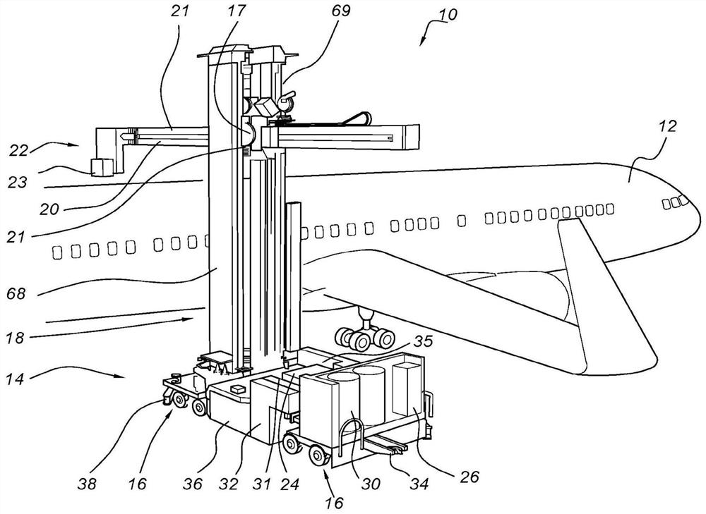
[0030] FIG. 1 shows a perspective view of a robotic system 10 for surface treatment of vehicles. Although system 10 is shown and described as a paint removal system that uses a high power laser to ablate a coating by scanning the laser across the surface of aircraft 12, it should be understood that system 10 may be used to provide many different surface treatments, such as spray coating, Sanding, direct printing, applying or removing other coatings or surface treatments, cleaning, scraping, surface scanning or repairing. Additionally, system 10 may be used with other vehicles or structures such as helicopters, boats, trucks, automobiles, underwater vehicles, aircraft; or any vehicle or structure that involves large areas and / or complex positioning to reach all surfaces.

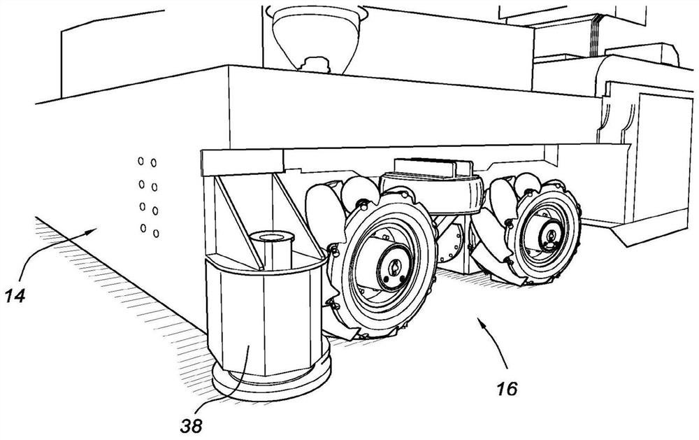
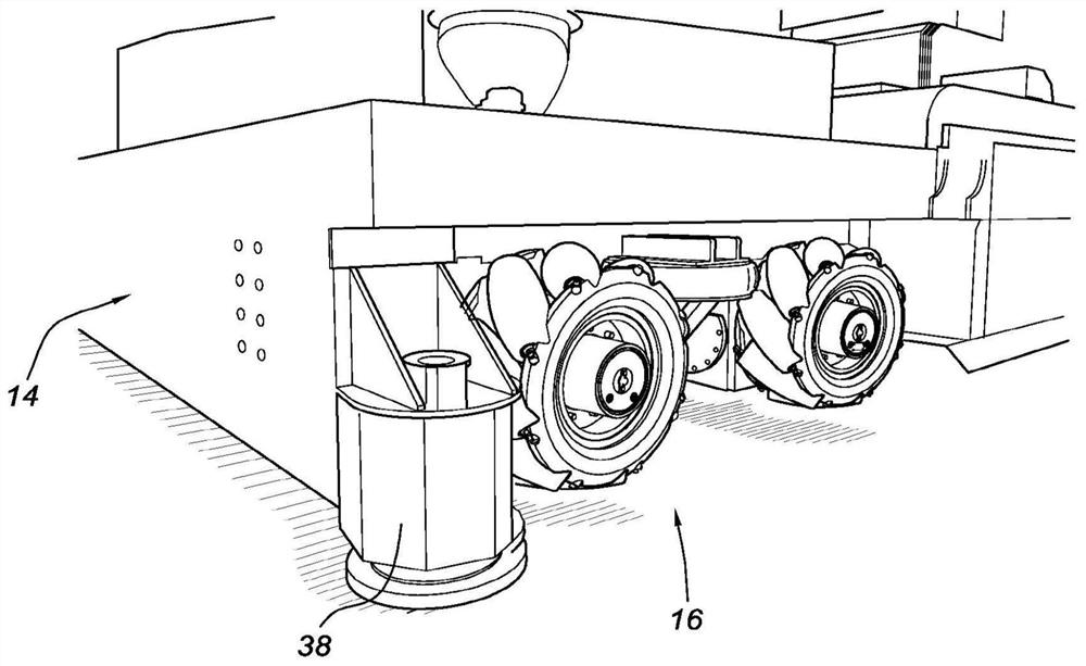
[0031] System 10 is a self-contained surface preparation system having a mobile base 14 connected to an omni bogie 16 . The bed uses four bogies 16 which can be moved in any direction by using two sets of Me...


PUM


Abstract

A robotic surface treatment system includes an omnidirectional base vehicle; a mast extending from the base vehicle; an arm extending from the mast and moveable in relation to the mast; a wrist connected to a distal end of the arm; and a surface treatment system extending from the base to the wrist through an inside of the mast, arm and wrist.

Description

Background technique [0001] The surface treatment of aircraft is an important task not only during manufacture, but also in aircraft maintenance. Various surface treatments may include removal / stripping of organic / inorganic materials delaminated on the substrate or substrate, inspection of the material and substrate to enable actual specification of the material or substrate, repair and / or correction The specification of a material or substrate, and the coating, printing, or adhesive covering of a material or substrate in one or more layers to meet certain specifications. The exterior paint of an aircraft must be in a sufficiently good condition to enable the aircraft to perform optimally and safely during operation. Small scratches or chipped sections of paint can affect aircraft performance. Therefore, it is necessary to periodically completely remove the exterior paint and apply new paint. However, paints used on the exterior surfaces of aircraft are not easily removable...

Claims


Application Information

Patent Timeline
IPC IPC(8): B25J5/00B64F5/40
CPCB25J5/007B64F5/40B25J11/0075B25J11/005B25J13/089
Inventor 格林·R·巴特利特杰里米·K·佐斯威廉·C·弗兰尼根彼得·博伊金克
Owner 美国西南研究院
Learn More