Side wall clamping and pressing type seed metering device

A seed metering device and seed technology, which is applied to sowing, single-grain seeding machines, planting machine parts, etc., can solve the problems of long manufacturing process, waste of seeds, and difficult manufacturing, etc., and achieve the effect of simple structure, easy manufacturing, and low cost

Pending Publication Date: 2021-04-02
JILIN DONGBEINIU SCI & TECH CO LTD
View PDF0 Cites 2 Cited by
  • Summary
  • Abstract
  • Description
  • Claims
  • Application Information

AI Technical Summary

Problems solved by technology

[0004] The existing problems are that the special chassis materials are expensive and difficult to manufacture, the structure of the seed parts is complex, the manufacturing process is long, and the processing is difficult. Several extension springs form a ring-shaped extension spring ring, which causes the force direction of the extension spring to deviate from the axis of the extension spring. , the tension spring is not in the correct stress state and is easily damaged. The above reasons make the existing mechanical precision seeding device complex in structure, difficult to manufacture, high in cost, low in safety, and short in service life.
The existing problem is: when the seed-taking clip block is used to take seeds in the seed bin, it is easy to get more than one seed. Although the arc section of the variable diameter makes the seed-picking clip block gradually press the side wall of the seed ring to realize the seed collection, the small-diameter arc section makes the The seed clamp block is in the clamping state, which can remove redundant seeds, but there is also a phenomenon that the redundant seeds cannot be removed. As a result, it not only causes waste of seeds, increases production costs, but also causes two seeds to be repeatedly sown in one seed pit. Thinning seedlings after emergence

Method used


Image

  • Side wall clamping and pressing type seed metering device
  • Side wall clamping and pressing type seed metering device
  • Side wall clamping and pressing type seed metering device

Examples


Embodiment Construction

[0022] The present invention will be further described below in conjunction with the accompanying drawings and embodiments.

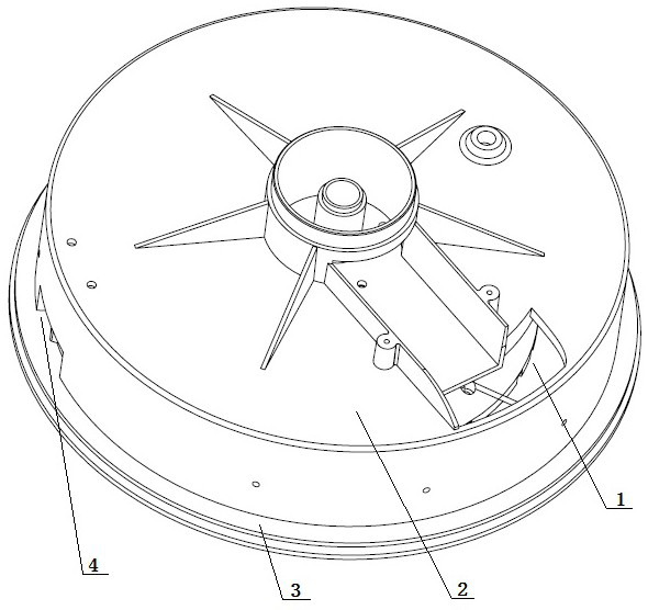
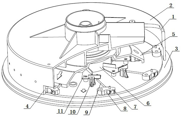
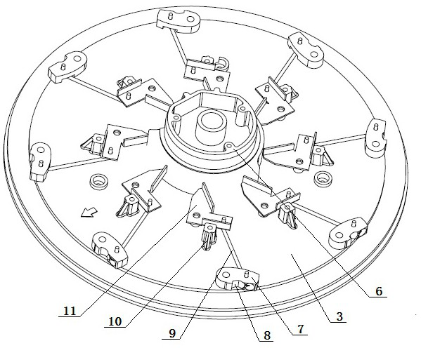
[0023] see Figure 1-5 , Embodiment 1, the present embodiment is a kind of side wall clamping type seed metering device, which includes chassis 3, cam 6, clamping type seed taking assembly, partition cover 5 and seed bin cover 2, and the above described chassis 3 is provided with the same The cam 6 of the shaft is matched with a gap, and the eight clamp-type seed-taking components are placed on the chassis 3 and arranged evenly along the circumference. One end of the clamp-press-type seed-taking component extends into the partition 5 and contacts the side wall of the cam 6. The partition cover 5 is placed on the cam 6 and the pinch type seed-taking assembly, and is sleeved on the cam 6 with a clearance fit. The seed bin cover 2 is placed on the chassis 3, and the mouth is in contact with the chassis 3. The seed bin cover 2. The inner side wall is in co...


PUM


Abstract

The invention relates to a side wall clamping and pressing type seed metering device which comprises a chassis, a cam, a clamping and pressing type seed taking assembly, a separation cover and a seedbin cover. The seed metering device is characterized in that a through hole is formed in the middle of the cam, the upper end of the cam is a connecting end, and the lower end of the cam is a workingend; a first convex section, a first concave section, a second convex section, a third convex section and a second concave section are sequentially arranged on the peripheral surface of the working end of the cam anticlockwise; and the first convex section is a seed selection process, the first concave section is a vibration seed scooping process, the second convex section is a seed determining process, the third convex section is a seed clamping, compacting and conveying process, and the second concave section is used for releasing the clamped seeds, so that a complete seed taking process ofscooping the seeds, selecting the seeds through vibration, determining the seeds, clamping and compacting the seeds, conveying the seeds and releasing the clamped seeds is achieved.

Description

technical field [0001] The invention belongs to agricultural machinery, in particular to a planter, which is a side wall clamping type seed metering device. Background technique [0002] Seeder has been widely used as a kind of agricultural machinery, and the precision seeder of prior art includes mechanical type seed metering device, electronic air suction type seed metering device and electronic air blowing type seed metering device. [0003] The mechanical precision sowing and metering device of the prior art includes a chassis, on which several groups of lugs are arranged along the periphery, and cams are arranged in the middle of the chassis and in the lugs, and the top surface of the cam is a working surface with ups and downs, and the seed can be harvested. One end of the seed-taking part is located on the working surface of the cam, and the other end is located in the seed bin. The end of the seed-taking part in the seed bin is in real-time contact with the bottom su...

Claims


Application Information

Patent Timeline
Patent Type & Authority Applications(China)
IPC IPC(8): A01C7/20A01C7/04
CPCA01C7/04A01C7/20A01C7/208
Inventor 辛力赵永辉孙海钊
Owner JILIN DONGBEINIU SCI & TECH CO LTD
Why Eureka
Try Eureka