Method for measuring forward tensile strength of welding spots and fixtures

A tensile strength and solder joint technology, which is applied in the field of welding testing, can solve the problems of inability to realize a square box, increase the test cost, and test difficulties, so as to overcome the unfavorable formability of sheet metal parts, and the measurement method is simple and easy to operate. strong effect

Active Publication Date: 2010-12-01
CHERY AUTOMOBILE CO LTD
View PDF4 Cites 8 Cited by
  • Summary
  • Abstract
  • Description
  • Claims
  • Application Information

AI Technical Summary

Problems solved by technology

This method can basically overcome the defect that the deformation of the tensile surface where the solder joint is located is not uniform, but this method has an obvious defect: it is mainly aimed at materials with low strength and good formability, that is to say, in the patent The shape of the square box of the test plate is realized by stamping, which requires a material with good formability to achieve
However, at present, high-strength steel and ultra-high-strength steel are generally used in automobiles to achieve the purpose of lightweighting. These materials have poor formability and require special treatment to achieve molding.
If direct stamping will not be able to achieve the shape of a square box, it will bring great difficulties to the test, and the cost of the test will also be greatly increased

Method used


Image

  • Method for measuring forward tensile strength of welding spots and fixtures
  • Method for measuring forward tensile strength of welding spots and fixtures
  • Method for measuring forward tensile strength of welding spots and fixtures

Examples


Embodiment 1

[0027] The method for measuring the forward tensile strength of solder joints of the present embodiment may further comprise the steps:

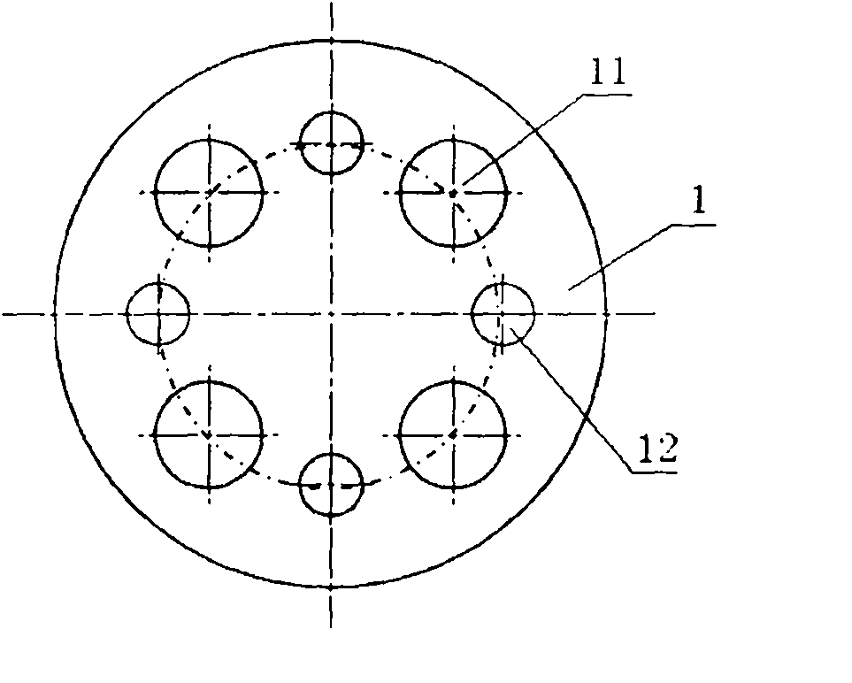
[0028] A: If figure 1 As shown, first two circular test plates 1 of the same size are stacked together concentrically, and then eight through holes with the same position and size are drilled on the two test plates 1, wherein each test plate 1 The through-holes on the top are evenly distributed on a circle, and the through-holes include four first through-holes 11 with larger diameters and four second through-holes 12 with smaller diameters, the first through-holes 11 and the second through-holes The holes 12 are arranged at intervals; the thickness of the test plate 1 is between 0.5-2.5 mm, and the surface is required to be smooth and flat, not corroded, flat and uniform in thickness;

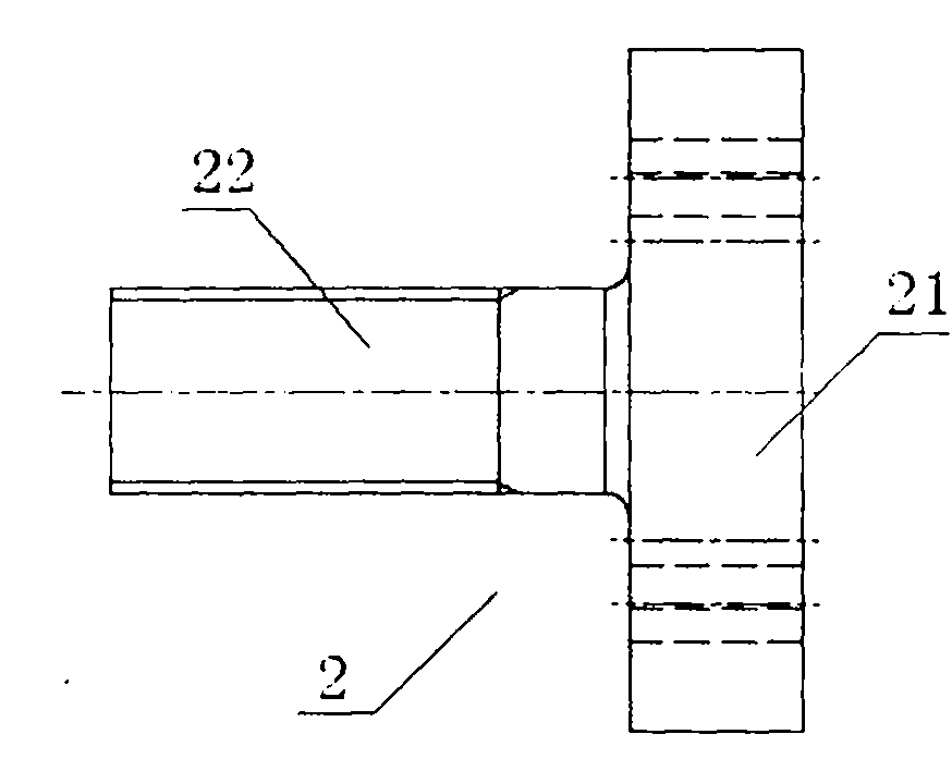
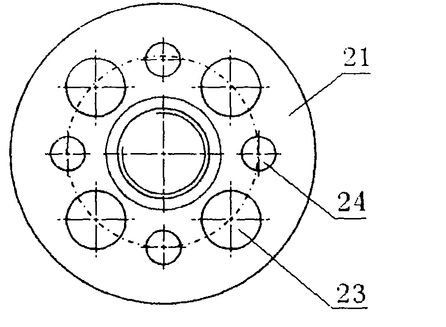
[0029] B: if figure 2 , 3 As shown, two fixtures 2 with mounting surfaces 21 and clamping ends 22 are selected, and through holes 23, 24 with the same p...


PUM

PropertyMeasurementUnit
thicknessaaaaaaaaaa

Abstract

The invention provides a method for accurately measuring forward tensile strength of welding spots and fixtures which are not limited by mouldability of a material. The method comprises the following steps: firstly drilling through holes of the same position and size on two test boards, wherein the through holes are uniformly distributed on one circumference and comprise first through holes with larger bore diameter and second through holes with smaller bore diameter, and the first through holes and the second through holes have equal number and alternately arranged; selecting two fixtures, and drilling through holes with the same position and size as those of the test boards on mounting surfaces of the two fixtures; stacking the two test boards together for spot welding to form the welding spots at the center of the circumference of the first through holes and the second first through holes, and respectively fixing the fixtures with the test boards at the same side by bolts and nuts; and finally stretching the two fixtures at a certain stretching speed until the welding spots of the test boards are ruptured, recording experimental data and carrying out tensile load-displacement curve analysis.

Description

technical field [0001] The invention belongs to the technical field of welding testing, and in particular relates to a method and a fixture for measuring the forward tensile strength of solder joints. Background technique [0002] Spot welding has the advantages of light weight, high static strength, good reliability, stable performance and easy automation. It has been widely used as a structural connection method for modern automobile bodies. Generally speaking, more than 90% of the welding points of car bodies will use spot welding. The failure of the solder joints of the body is mainly due to the action of the comprehensive force, which leads to the cracking of the solder joints. Therefore, in order to ensure the safety and reliability of the body structure, considering the extreme force that the solder joints can withstand has become the focus of current research. [0003] At present, there are relatively few studies on the spot welding tensile test method. In the paten...

Claims


Application Information

Patent Timeline
Patent Type & Authority Applications(China)
IPC IPC(8): G01N3/08G01N3/04
CPCG01N3/00G01N3/08B23K31/12G01N2203/0017
Inventor 金泉军曾泳吴沈荣徐有忠
Owner CHERY AUTOMOBILE CO LTD
Why Eureka
Try Eureka