

Efficient dust removal device for building construction protection
A technology of building construction and dust removal device, which is applied in the direction of using liquid separation agent, separation of dispersed particles, chemical instruments and methods, etc. It can solve the problems of small dust removal operation area, affect the sight of staff, and reduce construction efficiency, so as to improve the scope of operation , to achieve the effect of dust reduction, to achieve the effect of sterilization and disinfection
- Summary
- Abstract
- Description
- Claims
- Application Information
AI Technical Summary
Problems solved by technology
Method used
Image

Examples
Embodiment 1
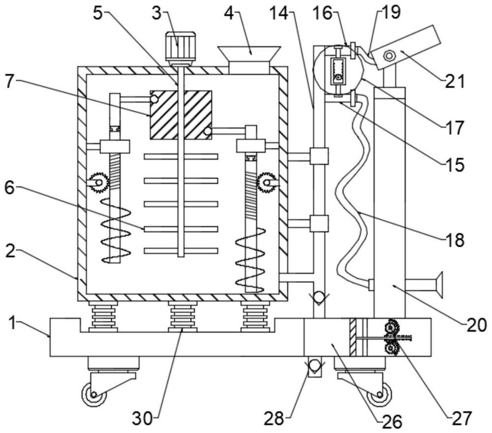
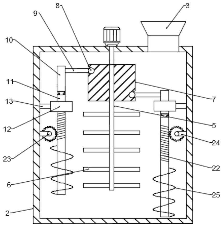
[0027] see figure 1 and 2 , in an embodiment of the present invention, a high-efficiency dust removal device for building construction protection includes a base 1, a water tank 2 is arranged above one side of the base 1, a rotating motor 3 is arranged at the center above the water tank 2, and the rotating motor 3 is provided with a liquid inlet 4 on one side, and the output end of the rotating motor 3 is fixedly connected to a rotating shaft 5, and a plurality of stirring rods 6 are arranged on the lower part of the rotating shaft 5, and a cylindrical cam 7 is fixedly sleeved on the upper part of the rotating shaft 5. A roller 8 is slidably connected to the chute of the outer contour of the cylindrical cam 7, the surface of the roller 8 is fixedly connected to a fixed rod 9, and the other side of the fixed rod 9 is connected to a movable rod 10, the movable A stirring shaft 11 is slidingly clamped under the rod 10, and a sleeve 12 is slidingly connected to the outside of the...
Embodiment 2
[0031] see image 3 , in this embodiment, multiple sets of compression springs 30 are fixedly installed between the bottom of the water tank 2 and the base 1; a compression chamber 26 is provided on one side of the base 1, and the upper part of the compression chamber 26 communicates with the bottom of the outlet pipe 14, A booster device 27 is provided on one side of the compression chamber 26 .
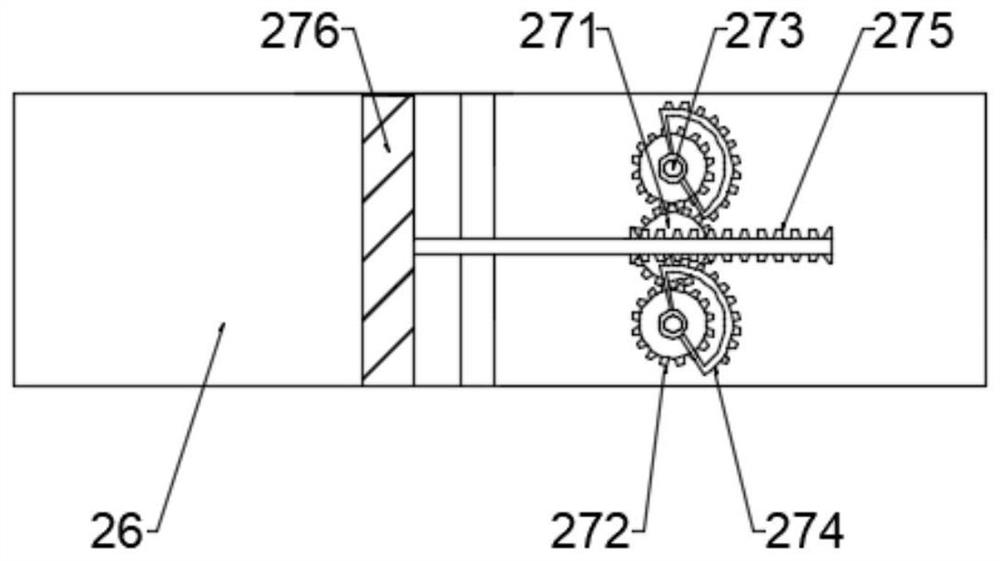
[0032]In this embodiment, the supercharging device 27 includes a driving gear 271, and a driven gear 272 is symmetrically meshed on both sides of the driving gear 271. A rotating rod 273 is arranged at the center of the driven gear 272, and the rotating rod 273 The upper end is fixed with a semicircular gear ring 274, and the middle of the semicircular gear ring 274 is alternately meshed with a rack bar 275, and the other end of the rack bar 275 is connected with a compression piston 276, and the compression piston 276 is arranged on In the compression chamber 26, the driving gear ...
Embodiment 3
[0035] see Figure 4 , in this embodiment, the adjustment device 17 includes an adjustment frame 171, and the upper and lower sides of the adjustment frame 171 are symmetrically provided with baffles 172, and the baffles 172 are respectively located inside the first conduit 15 and the second conduit 16, The end of the baffle plate 172 is provided with a limit block 173, the middle part of the adjustment frame 171 is provided with an incomplete gear 174, the inner walls of both sides of the adjustment frame 171 are symmetrically provided with rack plates 175, and the incomplete gear 174 It meshes with the rack plate 175, and when the incomplete gear 174 is rotated, it meshes with the rack plates 175 on the left and right sides respectively, driving the adjustment frame 171 to move upward or downward, so as to realize the adjustment of the first conduit 15 or the second conduit 16. closed.
PUM
 Abstract
Description
Claims
Application Information