Automatic industrial iron plate two-side grinding equipment

A kind of technology for industrial use and equipment, which is applied in the field of equipment for grinding both sides of iron plates for automatic industrial use, which can solve the problems of insufficient grinding and low grinding efficiency, and achieve the effect of improving efficiency

Pending Publication Date: 2021-04-02
黎旭芬
View PDF7 Cites 2 Cited by
  • Summary
  • Abstract
  • Description
  • Claims
  • Application Information

AI Technical Summary

Problems solved by technology

[0004] In order to overcome the shortcomings of manual grinding, low grinding efficiency and insufficient grinding, the technical problem is to pro

Method used


Image

  • Automatic industrial iron plate two-side grinding equipment
  • Automatic industrial iron plate two-side grinding equipment
  • Automatic industrial iron plate two-side grinding equipment

Examples


Embodiment 1

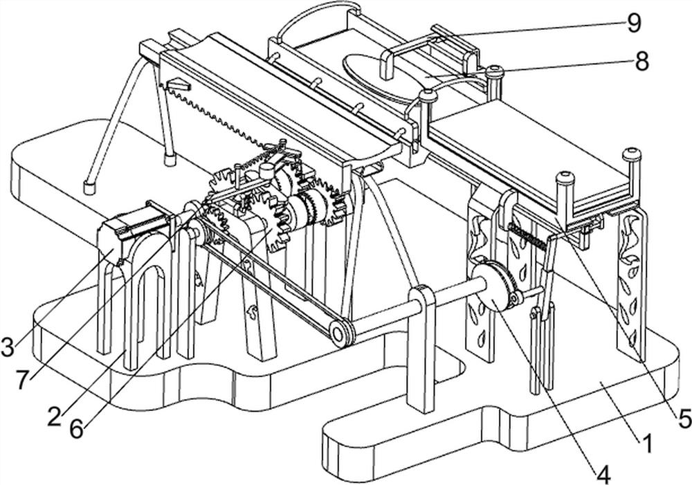
[0094] A kind of equipment for grinding both sides of iron plate in automatic industry, such as figure 1 As shown, it includes a bottom plate 1, a first support frame 2, a servo motor 3, a feeding mechanism 4, a placing mechanism 5, a rotating mechanism 6, a toggle mechanism 7, a grinding mechanism 8 and a fixing mechanism 9. The top front side of the bottom plate 1 is provided with The first support frame 2, the top of the first support frame 2 is provided with a servo motor 3, the right side of the top of the bottom plate 1 is provided with a feeding mechanism 4, the top of the feeding mechanism 4 is provided with a placement mechanism 5, and the top front of the bottom plate 1 is provided with a rotating mechanism 6, A toggle mechanism 7 is arranged above the rotating mechanism 6 , a grinding mechanism 8 is arranged at the top middle of the bottom plate 1 , and a fixing mechanism 9 is arranged above the polishing mechanism 8 .

[0095] The staff puts the iron plate in the p...

Embodiment 2

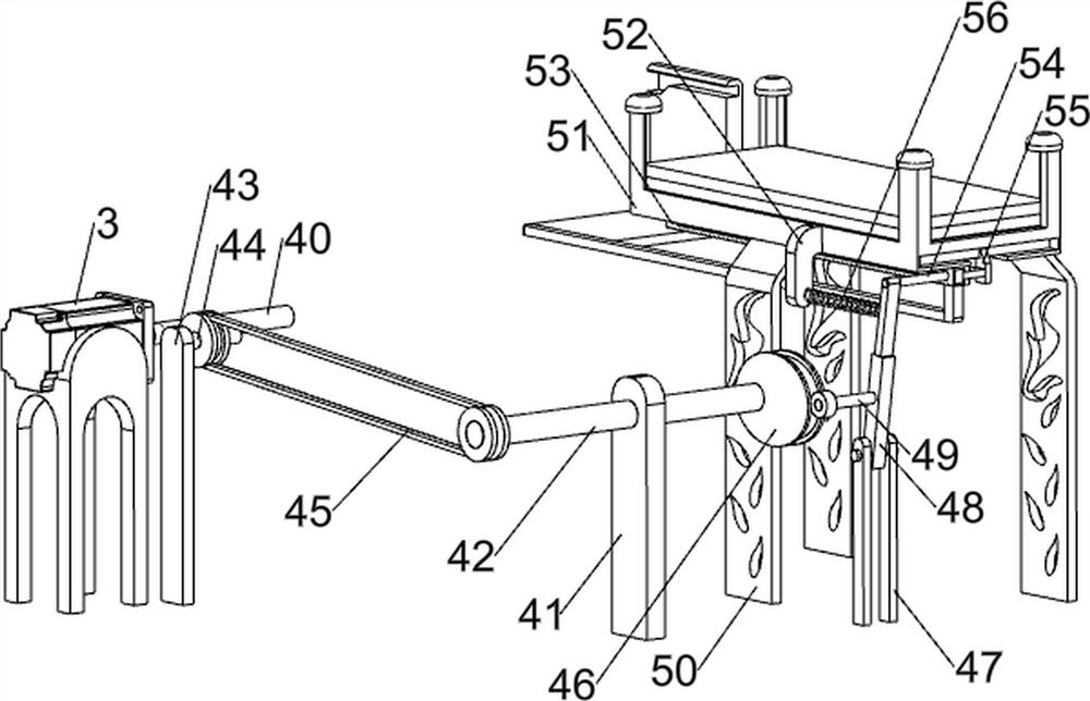
[0097] On the basis of Example 1, such as Figure 2-8 As shown, the feeding mechanism 4 includes a first rotating shaft 40, a first supporting plate 41, a second rotating shaft 42, a second supporting plate 43, a third rotating shaft 44, a pulley assembly 45, a convex circle 46, a second supporting frame 47, a second supporting frame 47, and a second rotating shaft 44. A connecting plate 48, the first connecting rod 49, half gears 410 and full gears 411, the output end of the servo motor 3 is provided with the first rotating shaft 40, the first rotating shaft 40 is provided with the half gear 410, and the bottom right part of the bottom plate 1 is provided with the second A support plate 41, the first support plate 41 is provided with a second rotating shaft 42 in rotation, the bottom plate 1 top front side is provided with a second support plate 43, and the second support plate 43 is rotatably provided with a third rotating shaft 44. A full gear 411 is provided on the rotatin...


PUM


Abstract

The invention relates to equipment for polishing two sides, in particular to automatic industrial iron plate two-side grinding equipment. The automatic industrial iron plate two-side grinding equipment does not need manual grinding, and is high in grinding efficiency and sufficient in grinding. The automatic industrial iron plate two-side grinding equipment comprises a bottom plate used for installing the whole equipment, a first supporting frame arranged on one side of the top of the bottom plate, a servo motor arranged at the top of the first supporting frame, a feeding mechanism arranged onone side of the top of the bottom plate, and a placing mechanism arranged above the feeding mechanism. According to the grinding equipment, through cooperation of a third guide plate, a wedge-shapedrod and a third spring, a second connecting rod drives the third guide plate to move left and right, so that the wedge-shaped rod moves along a groove of the third guide plate, and an iron sheet is clamped or loosened under cooperation of the third spring.

Description

technical field [0001] The invention relates to a device for grinding both sides, in particular to a device for grinding both sides of an iron plate used in the automation industry. Background technique [0002] Iron plates are commonly used building materials in construction. Iron plates are prone to rust during long-term storage. The existing construction sites often use manual derusting methods, using emery cloth, sandpaper, scrapers, wire brushes, hammer chisels, etc. Tools to remove rust, scale and impurities by hand shoveling, grinding, scraping and sweeping. Manual grinding is labor-intensive, low in efficiency, and poor in labor protection. Generally, rust remains after cleaning, and the quality is unstable. Moreover, the current grinding device has poor grinding effect, especially when grinding rusty iron plates. Larger and the rust on it will cause certain damage to the grinding device, so that the grinding efficiency is low and the grinding is not sufficient. ...

Claims


Application Information

Patent Timeline
IPC IPC(8): B24B7/17B24B27/033B24B41/00B24B41/06B24B47/04B65G59/06
CPCB24B7/17B24B27/033B24B41/005B24B41/06B24B47/04B65G59/067
Inventor 黎旭芬
Owner 黎旭芬
Why Eureka
Try Eureka