Biological fermentation condition detection device used during biological fermentation

A bio-fermentation and detection device technology, which is applied in the field of detection devices, can solve problems such as difficult detection of fermentation conditions, and achieve the effect of simplifying the operation process and making it easy to take out

Pending Publication Date: 2021-04-02
广州万为通达科技有限公司
View PDF6 Cites 0 Cited by
  • Summary
  • Abstract
  • Description
  • Claims
  • Application Information

AI Technical Summary

Problems solved by technology

[0004] In order to overcome the shortcomings of complex operation and difficult detection of fermentation conditions, the technical problem of the present invention is to provide a detection device for biological fermentation conditions during biological fermentation that can detect fermentation conditions at different depths, assist in detecting the environment of the fermentation tank, and facilitate observation

Method used


Image

  • Biological fermentation condition detection device used during biological fermentation
  • Biological fermentation condition detection device used during biological fermentation
  • Biological fermentation condition detection device used during biological fermentation

Examples


Embodiment 1

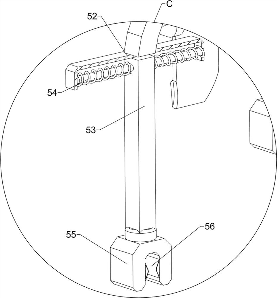
[0076] A device for detecting biological fermentation conditions during biological fermentation, such as figure 1 As shown, it includes a support plate 1, a pressing assembly 2, a retrieving assembly 3 and a clamping assembly 4. The supporting plate 1 is slidably connected to the pressing assembly 2, and the lower side of the pressing assembly 2 is connected to the retrieving assembly 3. A clamping assembly 4 is connected to the upper side of the support plate 1 .

[0077] When the device needs to be used, the user can place the device above the fermented product, push down the pressing assembly 2, and then continue to push down the pressing assembly 2, at this time the pressing assembly 2 is compressed to facilitate the removal of the fermented product , for the purpose of simplifying the operation process, the downward movement of the pressing component 2 drives the retrieving component 3 to move downward, and then makes the retrieving component 3 rotate forward, and the fer...

Embodiment 2

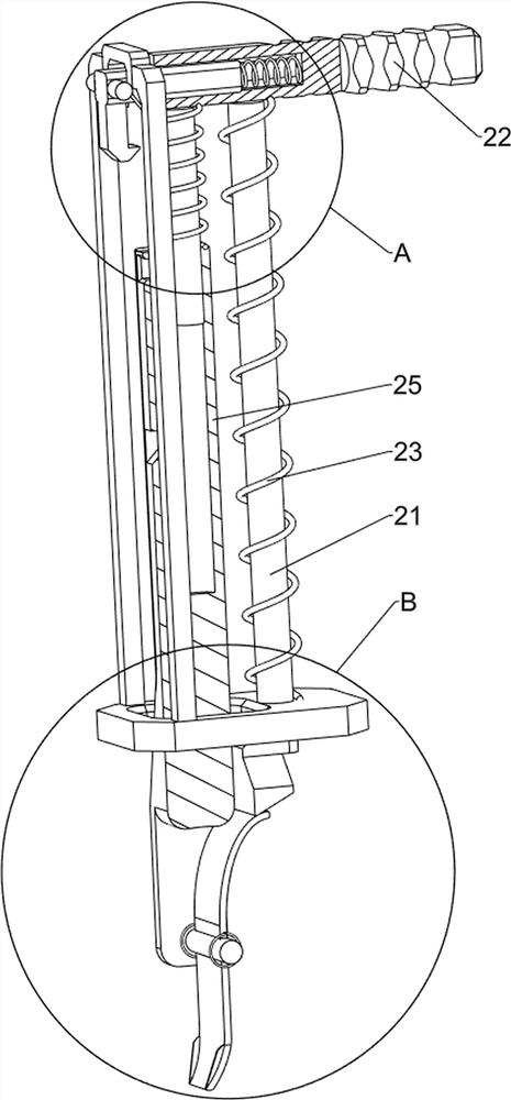
[0079] On the basis of Example 1, such as figure 2 and image 3 As shown, the pressing assembly 2 includes a first connecting rod 21, a handle 22, a first spring 23, a second connecting rod 24, a third connecting rod 25 and a second spring 26, and the support plate 1 is slidably connected with a second A connecting rod 21, the top of the first connecting rod 21 is connected with a handle 22, the first connecting rod 21 is wound with a first spring 23, the lower side of the handle 22 is connected with a second connecting rod 24, and the second connecting rod 24 slides A third connecting rod 25 is connected in a formula, the third connecting rod 25 passes through the support plate 1 , and the second connecting rod 24 is wound with a second spring 26 .

[0080] When the device needs to be used, the user can place the device above the fermented product, push the handle 22 downward, and the downward movement of the handle 22 drives the first connecting rod 21 to slide downward in...


PUM


Abstract

The invention relates to a detection device, in particular to a biological fermentation condition detection device used during biological fermentation. The invention aims to provide the biological fermentation condition detection device used during biological fermentation, which can detect fermentation conditions of different depths, assists in detecting the environment of a fermentation tank andis convenient to observe. According to the technical scheme, the biological fermentation condition detection device used during biological fermentation comprises a pressing-down assembly, wherein thepressing-down assembly is connected into a supporting plate in a sliding mode; a material taking assembly, wherein the bottom side of the pressing-down assembly is connected with the material taking assembly; and a clamping assembly, wherein the top side of the supporting plate is connected with the clamping assembly. Through cooperation of a first connecting rod, a grip, a second connecting rod and a third connecting rod, the purposes of conveniently taking out fermented materials and simplifying the operation process are achieved.

Description

technical field [0001] The invention relates to a detection device, in particular to a detection device for biological fermentation conditions during biological fermentation. Background technique [0002] The microbial fermentation process is divided into aerobic fermentation and anaerobic fermentation according to the requirements of fermentation conditions. The aerobic fermentation method includes liquid surface culture fermentation, fermentation on the surface of porous or granular solid medium, and aerobic submerged fermentation. Anaerobic fermentation Submerged fermentation without oxygen is used. Biological fermentation is an important component of bioengineering. Microorganisms can use carbohydrates to ferment to produce various industrial solvents and chemical raw materials. This fermentation process is often carried out in closed fermentation tanks. Through technical means Adjust the environment in the fermenter to make the biological fermentation reach the best sta...

Claims


Application Information

Patent Timeline
Patent Type & Authority Applications(China)
IPC IPC(8): C12M1/36C12M1/34C12M1/26C12M1/00
CPCC12M23/48C12M33/00C12M41/00C12M41/48
Inventor 高翠翠
Owner 广州万为通达科技有限公司
Why Eureka
Try Eureka