
Self-locking hydraulic cylinder

A hydraulic cylinder and self-locking technology, which is applied in fluid pressure actuating devices, mechanical equipment, etc., can solve the problems of large space occupation, inconvenient maintenance and use, and increased oil circuits, and achieve reliable use, reliable locking, and simplified oil. road effect

Inactive Publication Date: 2021-04-02
符鹏
View PDF0 Cites 1 Cited by
  • Summary
  • Abstract
  • Description
  • Claims
  • Application Information

AI Technical Summary

Problems solved by technology

When the hydraulic lock is kept at a certain position for a long time, due to problems such as pressure oil leakage, the accuracy often cannot meet the requirements, and when the oil circuit fails, the accuracy and reliability cannot be guaranteed; the hydraulic lock often requires a one-way valve , reversing valve and other auxiliary components cooperate to realize the locking circuit. The use of these components makes the whole device occupy a large space. At the same time, the increase in the oil circuit is prone to leakage, causing inconvenience in maintenance and use.

Method used


Image

  • Self-locking hydraulic cylinder
  • Self-locking hydraulic cylinder
  • Self-locking hydraulic cylinder

Examples


Embodiment Construction

[0018] The present invention will be further described in detail below in conjunction with the accompanying drawings and embodiments.

[0019] Such as Figure 1-3 Shown is a preferred embodiment of the present invention.

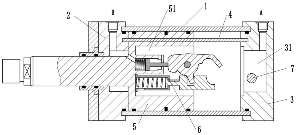
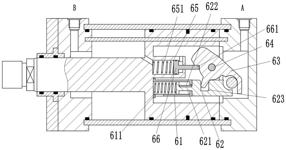
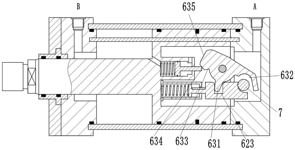
[0020] A self-locking hydraulic cylinder, comprising a cylinder body 1, a left end cover 2, a right end cover 3, a limit rod 4, a piston body 5, a locking assembly 6 and a self-locking rod 7; the cylinder body 1 is cylindrical, and the One end of the cylinder body 1 is fixedly provided with a left end cover 2, and the other end of the cylinder body 1 is fixedly provided with a right end cover 3, and a limit rod 4 is arranged at an eccentric position between the left end cover 2 and the right end cover 3, and the cylinder body 1 is slidably connected with a piston body 5 along the horizontal direction, and the piston body 5 is slidably connected with the limit rod 4; the opposite end of the piston body 5 and the left end cover 2 is extended to the left, and ...


PUM


Abstract

The invention relates to a self-locking hydraulic cylinder which comprises a cylinder body, a left end cover, a right end cover, a limiting rod, a piston body, a locking assembly and a self-locking rod. The cylinder body is cylindrical, the left end cover is fixedly arranged at one end of the cylinder body, the right end cover is fixedly arranged at the other end of the cylinder body, the limitingrod is arranged at the eccentric position between the left end cover and the right end cover, the piston body is connected into the cylinder body in the horizontal direction in a sliding mode, and the piston body is connected with the limiting rod in a sliding mode. The end, opposite to the left end cover, of the piston body extends leftwards to be provided with a piston rod extending out of theleft end cover. A rod cavity is formed between the piston body and the left end cover in the cylinder body, and a rodless cavity is formed between the piston body and the right end cover. A port B communicating with the rod cavity is formed in the side surface of the left end cover, and a port A communicating with the rodless cavity is formed in the side surface of the right end cover. A first mounting cavity is formed in the end face, opposite to the right end cover, of the piston body, and a locking assembly is arranged in the first mounting cavity. A cavity is formed in the right end cover,a self-locking rod matched with the locking assembly is arranged in the cavity, the self-locking rod is fixedly connected with the right end cover, and the axis of the self-locking rod is perpendicular to the axis of the piston body. The hydraulic cylinder does not need to be provided with a hydraulic control one-way valve, an oil way is simplified, locking is reliable due to the fact that mechanical locking is adopted, the structure is simple, and manufacturing is convenient.

Description

technical field [0001] The invention belongs to the field of hydraulic cylinders, in particular to a self-locking hydraulic cylinder. Background technique [0002] Self-locking hydraulic cylinders have a wide demand in engineering fields, such as in metallurgy, coal mines, construction machinery, sanitation vehicles and other mechanical fields of lifting and landing equipment. In order to prevent the workpiece from external force or self-weight (hydraulic pressure) when it stops working, hydraulic components The displacement occurs under the action of vertical cylinder), and the hydraulic cylinder needs to be locked. [0003] At present, the hydraulic cylinder mainly relies on sealing the pressure oil to lock the hydraulic cylinder, which is easy to leak, and "negative pressure effect" and "soft leg phenomenon" occur. Although there are many improved products, the above problems have not been fundamentally solved. When the hydraulic lock is kept at a certain position for a ...

Claims


Application Information

Patent Timeline
IPC IPC(8): F15B15/14F15B15/20F15B15/26
CPCF15B15/1423F15B15/261F15B2215/30
Inventor 符鹏吴春保魏新
Owner 符鹏
Features
  • Generate Ideas
  • Intellectual Property
  • Life Sciences
  • Materials
  • Tech Scout
  • Unparalleled Data Quality
  • Higher Quality Content
  • 60% Fewer Hallucinations
Learn More