
An electro-hydraulic control reversing valve with internal pressure relief function

An electro-hydraulic control reversing valve and reversing valve technology, which is applied to servo meter circuits, fluid pressure actuators, servo motor components, etc., can solve the problems of lack of multi-way reversing valve core, heavy structure, and use restrictions There are many problems, so as to ensure the safety of maintenance, simplify the oil circuit of the system, and facilitate the use

Active Publication Date: 2017-11-07
BEIJING TIANMA INTELLIGENT CONTROL TECH CO LTD +1
View PDF3 Cites 0 Cited by
  • Summary
  • Abstract
  • Description
  • Claims
  • Application Information

AI Technical Summary

Problems solved by technology

At present, there are two types of electromagnetic reversing valves put into use on coal shearers: one is the ordinary on-off electromagnetic reversing valve. Because the working pressure of the electromagnetic valve is low and the difference from the main oil circuit is large, an additional oil pump is required as the electromagnetic valve. The liquid supply increases the complexity of the system; the electromagnetic reversing valves are plate-connected, and the structure is bulky and not compact enough; the other is an electro-hydraulic proportional multi-way reversing valve, which has better control characteristics than the previous one, but it is completely from the previous one. Imported from abroad, the cost is higher
[0004] The integral pilot electromagnetic reversing valve in the prior art, such as CN85202016U, is a diaphragm valve with a simple structure and poor impact resistance, which is not suitable for the underground working environment, and has no unloading function, so it cannot be used for coal mining In machine control; while CN202790679U, CN201521675U and other electromagnetic reversing valves do not have the ability to set multi-way reversing valve cores, and cannot realize functions such as zero-position unloading and return liquid separation. The work of heavy equipment such as underground coal mining machines requires

Method used


Image

  • An electro-hydraulic control reversing valve with internal pressure relief function
  • An electro-hydraulic control reversing valve with internal pressure relief function
  • An electro-hydraulic control reversing valve with internal pressure relief function

Examples


Embodiment 2

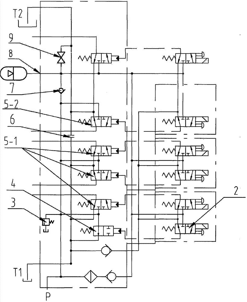
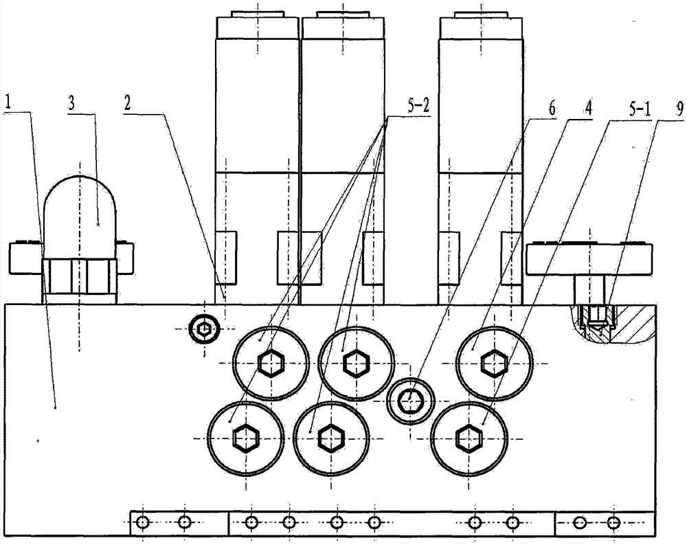
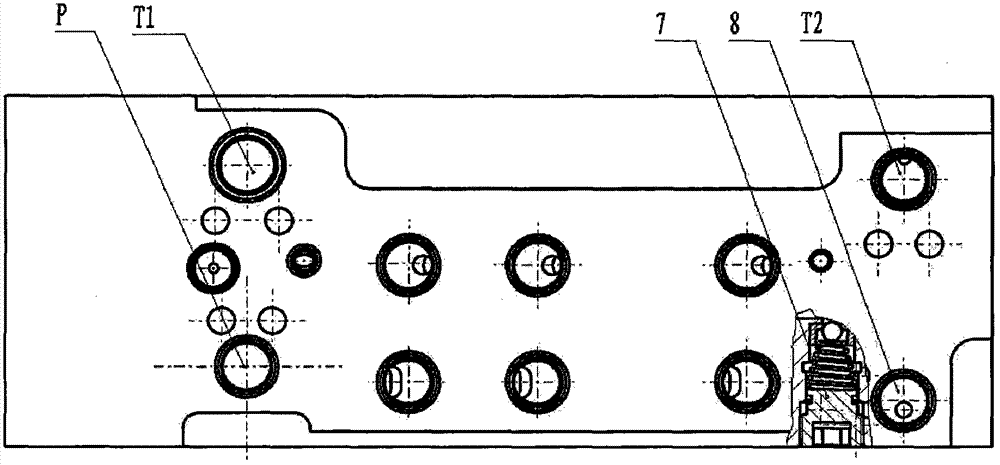
[0027] The schematic diagram of embodiment two, such as Figure 8 As shown, when the solenoid pilot valve is powered off, the unloading spool 4 disconnects the connection between the oil pump and the fuel tank; when the solenoid pilot valve is powered on, the oil pump is connected to the fuel tank; Figure 9 It is a specific implementation diagram of the integrated electro-hydraulic control reversing valve corresponding to the above schematic diagram. The difference is that there is an on-off valve in the unloading valve core. Oil pump and oil tank; when the electromagnetic pilot valve operates, the high-pressure control oil enters the back of the on-off valve, opens the on-off valve, connects the P port with the T2 port, and connects the oil pump and the oil tank.


PUM


Abstract

The invention provides an electro-hydraulic control reversing valve with an internal pressure relief function. The electro-hydraulic control reversing valve comprises electromagnetic pilot operated valves, a valve body, an unloading valve core and a reversing valve core. The electro-hydraulic control reversing valve is characterized in that the unloading valve core is controlled through the electromagnetic pilot operated valves, high-pressure and low-pressure state switching of a liquid supply system of the electro-hydraulic control reversing valve is achieved, a liquid return channel of the unloading valve core is communicated with main returned liquid of the electro-hydraulic control reversing valve, and a liquid inlet channel of the unloading valve core is communicated with an oil source. According to the electro-hydraulic control reversing valve, the system oil way is simplified, the electro-hydraulic control reversing valve is compact in structure and convenient to use, and safe, accurate, fast and reliable control over actions of a coal mining machine is achieved.

Description

technical field [0001] The invention relates to an electro-hydraulic control reversing valve used in the hydraulic system of an underground coal mining machine in a coal mine, in particular to an integrated valve with the functions of overflow and pressure stabilization, load unloading, liquid return separation, external accumulator and accumulator pressure relief. Type electro-hydraulic control reversing valve. Background technique [0002] Shearer is a kind of coal machine equipment with highly integrated mechanical, electrical and hydraulic systems. It is a key component of fully mechanized mining face equipment in coal mines and is of great significance to the safe, high-yield and efficient mining of coal. Generally speaking, the shearer can be divided into four parts functionally: cutting part, traction part, motor and electrical control device and other auxiliary devices. Among them, the cutting part is composed of rocker arm, roller and other parts, which are used to...

Claims


Application Information

Patent Timeline
Patent Type & Authority Patents(China)
IPC IPC(8): F15B13/02
CPCF15B13/02F15B2211/212
Inventor 王伟李继周刘晓萌吴会刚
Owner BEIJING TIANMA INTELLIGENT CONTROL TECH CO LTD
Learn More