
Method for calculating rotor forced excitation hot spot temperature of air-cooled non-salient pole synchronous phase modifier

A technology of hot spot temperature and calculation method, which is applied in calculation, computer-aided design, complex mathematical operations, etc., and can solve problems such as inability to accurately evaluate hot spot temperature

Active Publication Date: 2021-04-02
SHANGHAI ELECTRIC POWER GENERATION EQUIPMENT CO LTD +1
View PDF6 Cites 0 Cited by
  • Summary
  • Abstract
  • Description
  • Claims
  • Application Information

AI Technical Summary

Problems solved by technology

[0003] In the past, the forced excitation hot spot temperature of the air-cooled rotor winding was generally estimated roughly by using the copper weight and copper specific heat of the rotor winding. Strictly speaking, only the average temperature of the rotor winding can be obtained, but it cannot be accurately evaluated. hot spot temperature

Method used


Image

  • Method for calculating rotor forced excitation hot spot temperature of air-cooled non-salient pole synchronous phase modifier
  • Method for calculating rotor forced excitation hot spot temperature of air-cooled non-salient pole synchronous phase modifier
  • Method for calculating rotor forced excitation hot spot temperature of air-cooled non-salient pole synchronous phase modifier

Examples


Embodiment Construction

[0048] In order to make the present invention more comprehensible, preferred embodiments are described in detail below with accompanying drawings.

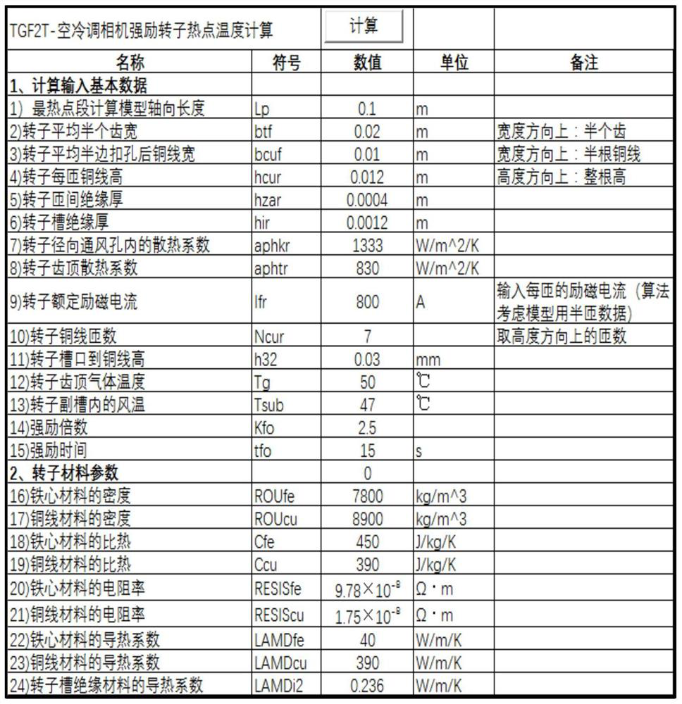
[0049] Such as image 3 As shown in the present invention, a method for calculating the rotor forced excitation hot spot temperature of an air-cooled hidden pole synchronous condenser comprises the following steps:

[0050] Step 1: Obtain the parameters of the input calculation model and material property parameters: only 24 parameters need to be input, including the axial length L of the calculation model of the hottest point section p (Unit: m), the average half tooth width of the rotor b tf (Unit: m), rotor half copper wire width b cuf (unit: m), the height of copper wire per turn of the rotor h cuf (unit: m), rotor turn-to-turn insulation thickness h zar (unit: m), rotor slot insulation thickness h ir (unit: m), the heat dissipation coefficient aph in the rotor radial ventilation hole kr (Unit: W / m 2 / K),, rotor addendu...


PUM


Abstract

The invention discloses a method for calculating the rotor forced excitation hot spot temperature of an air-cooled non-salient pole synchronous phase modifier, and the method comprises the steps of inputting a calculation model and forced excitation parameters, and dividing a model geometry into a discretized heat flow node topological connection diagram; and gradually determining the area, depth,thermal resistance, resistance, heating power and other parameters of each heat flow node, listing the energy conservation equation of each node by taking the node temperature as an unknown variable,forming an equation set, and solving the equation set to obtain the rotor winding forced excitation hot spot temperature of the air-cooled phase modifier. According to the invention, only 24 parameters need to be input, the rotor forced excitation hot spot temperature can be automatically calculated, the heat flow node topological graph can be automatically drawn, the requirements for air coolingnon-salient pole synchronous motor rotor forced excitation hot spot temperature calculation and curve drawing can be well met, and the purpose of conveniently, rapidly and accurately obtaining the air cooling rotor forced excitation hot spot temperature is achieved. The invention has the characteristics of less input data, simplicity and convenience in operation, quickness in calculation and drawing, concise and intuitive heat flow node topological connection diagram and the like.

Description

technical field [0001] The invention relates to a calculation method for the forced excitation hot spot temperature of the rotor of an air-cooled hidden pole synchronous condenser, which can be used in the calculation research and product design and development of the rotor forced excitation hot spot temperature of a distributed air-cooled hidden pole synchronous condenser, and belongs to the electromagnetic and The field of cooling design technology. Background technique [0002] The forced excitation requirements of the new generation of distributed air-cooled hidden-pole synchronous condenser are relatively high, and the calculation of the forced excitation hotspot temperature of its air-cooled rotor winding is an important link in product design and development. The accuracy of rotor forced excitation hotspot temperature calculation not only affects the determination of product design schemes, but also is closely related to the safety of air-cooled air-conditioning camer...

Claims


Application Information

Patent Timeline
IPC IPC(8): G06F17/11G06F30/20G06F119/08
CPCG06F17/11G06F30/20G06F2119/08
Inventor 钟后鸿曹志伟王继豪咸哲龙刘明慧
Owner SHANGHAI ELECTRIC POWER GENERATION EQUIPMENT CO LTD
Learn More