
A UAV-based design method for fine real-world 3D modeling of existing railway lines
A technology of 3D modeling and design methods, applied in 3D modeling, design optimization/simulation, CAD numerical modeling, etc., can solve problems such as prohibition of crossing lines, reduce workload, ensure accuracy of results, and improve safety Effect
Patent Information
- Authority / Receiving Office
- CN · China
- Patent Type
- Patents(China)
- Current Assignee / Owner
- Publication Date
- 2022-07-12
Smart Images
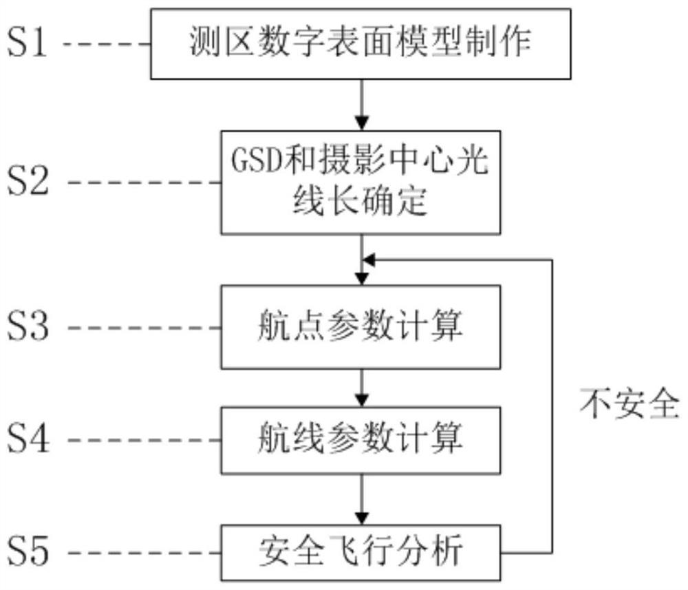
Figure 1 
Figure 2 
Figure 3
Abstract
Description
technical field
[0001] The invention belongs to the technical field of railway engineering survey and operation and maintenance, and in particular relates to a method for designing a flight belt based on an unmanned aerial vehicle for fine real scene three-dimensional modeling of existing railway lines. Background technique
[0002] With the rapid development of my country's high-speed railways, more and more work is involved in the surveying of existing lines in the railway survey stage. However, existing line surveys have shortcomings such as difficulties in going online, high operational safety hazards, and low operational efficiency.
[0003] In recent years, UAVs have become more and more widely used in environmental monitoring, power inspection, rail transit and other fields due to their advantages of low cost and flexible operation. Therefore, there are more and more practices using "UAV+" technology to solve existing line survey problems, and UAV 3D modeling aerial p...
Examples
Embodiment Construction
[0046] The following will describe in detail the UAV-based fine real scene 3D modeling air belt design method for existing railway lines of the present invention with reference to the accompanying drawings.
[0047] like figure 1 As shown, the method includes the following steps:
[0048] S1, obtaining digital surface model data along the railway line, which specifically includes the following steps:
[0049] S1-1, use the free 3D geographic information platform such as existing ledger data or sky map to create a 3D centerline file of the line, and measure a point every 20-50 meters according to the straight line segment and every 10-20 meters for the curved segment. A point, draw the existing line position;
[0050] S1-2, make the railway line position buffer zone; according to the railway line position direction, obtain the railway three-dimensional center line based on step S1-1, and make the buffer zone according to the range of 100 meters on the left and right sides of ...