
Display panel, display device and repairing method of display panel

A display panel and display area technology, applied in static indicators, instruments, etc., can solve the problems of damage to the detection circuit, short circuit of the signal line, affecting the display of the display panel, etc., to achieve the effect of ensuring the yield

Active Publication Date: 2021-04-02
HUBEI YANGTZE IND INNOVAION CENT OF ADVANCED DISPLAY CO LTD
View PDF6 Cites 4 Cited by
  • Summary
  • Abstract
  • Description
  • Claims
  • Application Information

AI Technical Summary

Problems solved by technology

[0003] When the signal port of the detection circuit or the signal port of the driver chip is exposed, the exposed signal port is easy to introduce static electricity to the detection circuit, and the static electricity introduced by the signal port will cause damage to the detection circuit, thereby making it electrically connected to the detection circuit The signal line of the display panel is short-circuited. When the signal line of the display panel is bound to the driver chip for display driving, it will affect the display of the display panel.

Method used


Image

  • Display panel, display device and repairing method of display panel
  • Display panel, display device and repairing method of display panel
  • Display panel, display device and repairing method of display panel

Examples


Embodiment Construction

[0026] The present invention will be further described in detail below in conjunction with the accompanying drawings and embodiments. It should be understood that the specific embodiments described here are only used to explain the present invention, but not to limit the present invention. In addition, it should be noted that, for the convenience of description, only some structures related to the present invention are shown in the drawings but not all structures.

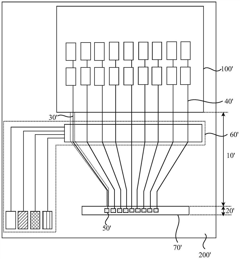
[0027] figure 1 is a schematic structural diagram of a display panel in the prior art provided by an embodiment of the present invention, such as figure 1 As shown, the display panel includes a display area 100' and a non-display area 200', the non-display area 200' includes a fan-out area 10' and a binding area 20', and the fan-out area 10' is located between the display area 100' and the binding area 20' 'between. The fan-out area 10' is provided with a plurality of fan-out lines 30', the first end of the fan-...


PUM


Abstract

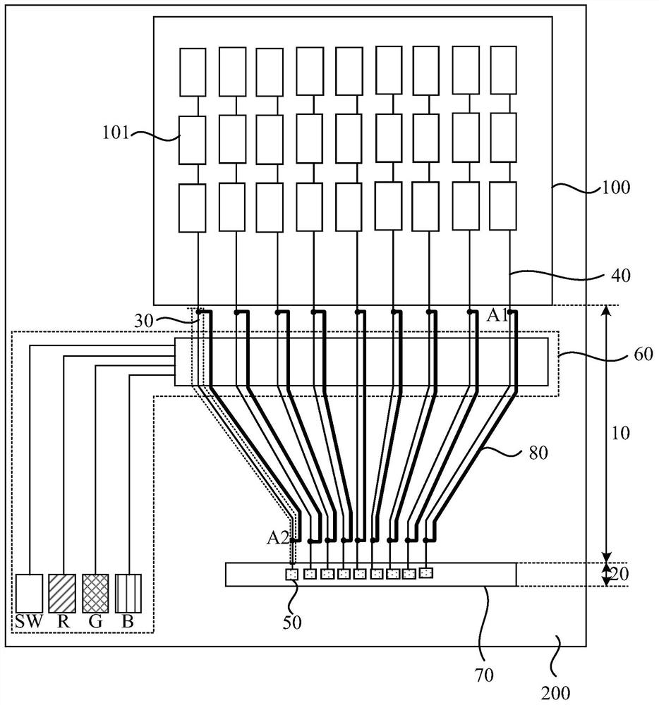
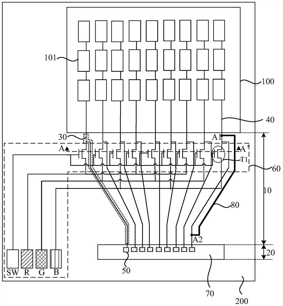
The invention discloses a display panel, a display device and a repairing method of the display panel. A fan-out area is provided with a plurality of first fan-out lines; the first ends of the first fan-out lines are electrically connected with at least one signal line of the display area; the second ends of the first fan-out lines are electrically connected with the binding bonding pad of the binding area; the fan-out area is also provided with a detection circuit; the output end of the detection circuit is electrically connected with the first fan-out wire; the detection circuit is used forinputting a test signal to the sub-pixels of the display area through the first fan-out lines before the display panel is bound with the driving chip; the fan-out area further comprises a plurality ofsecond fan-out lines; the second fan-out lines are connected with the first fan-out lines in parallel; the connection points of the first ends of the second fan-out lines and the first fan-out linesare first nodes; the connection points of the second ends of the second fan-out lines and the first fan-out lines are second nodes; the first nodes are located between the detection circuit and the display area; and the second nodes are located between the binding area and the display area, and the yield of the display panel is improved.

Description

technical field [0001] The invention relates to the technical field of display panels, in particular to a display panel, a display device and a repair method for the display panel. Background technique [0002] In the existing display panel, in order to improve the yield rate of the display panel and prevent defective products from flowing into the client, the display panel is generally checked by lighting before the display panel is bound to the driver chip, and the display panel is checked by inputting various analog signals. functional deficiencies. In order to increase the detection rate, a detection circuit is generally used to perform a lighting test on the display panel. Wherein, the detection circuit in the display panel inputs test signals to the sub-pixels in the display area through fan-out lines. [0003] When the signal port of the detection circuit or the signal port of the driver chip is exposed, the exposed signal port is easy to introduce static electricit...

Claims


Application Information

Patent Timeline
IPC IPC(8): G09G3/00
CPCG09G3/006
Inventor 顾家昌李远彭涛
Owner HUBEI YANGTZE IND INNOVAION CENT OF ADVANCED DISPLAY CO LTD
Learn More