
Mini LED backlight module and backlight source

A backlight module and backlight technology, applied in optics, nonlinear optics, instruments, etc., can solve the problem that the color gamut range cannot meet the application requirements of high-end scenes, the ultra-thin index cannot be truly achieved, and the overall brightness of the backlight cannot be achieved. To solve high-level problems, achieve the effect of improving the uniformity of light mixing and the viewing angle of light, satisfying mass industrial production, and improving the brightness of backlight

Pending Publication Date: 2021-04-02
NANJING UNIV OF TECH
View PDF0 Cites 5 Cited by
  • Summary
  • Abstract
  • Description
  • Claims
  • Application Information

AI Technical Summary

Problems solved by technology

[0006] Although the existing Mini LED backlight can achieve a certain effect, its color gamut range still cannot meet the application requirements of high-end scenes; at the same time, due to the performance of quantum dots, the overall brightness of the backlight cannot be very high, which affects its outdoor use effect; In addition, in order to achieve uniform light mixing, the existing backlight requires a diffuser plate to process the light, so the overall thickness of the backlight module is increased to a certain extent, and the ultra-thin index cannot be truly achieved.

Method used


Image

  • Mini LED backlight module and backlight source
  • Mini LED backlight module and backlight source
  • Mini LED backlight module and backlight source

Examples


Embodiment 1

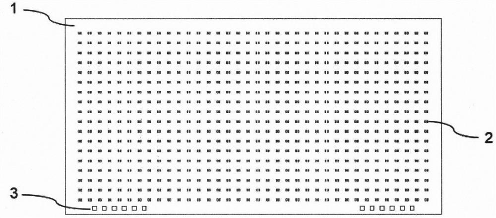
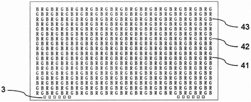
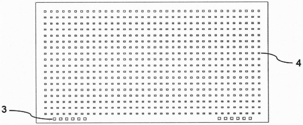
[0031] The Mini LED backlight device described in this embodiment is mainly composed of a substrate 1, a Mini LED chip 4, and an encapsulant 5. The substrate is used to carry the Mini LED chip and circuit design, such as figure 1 As shown, the substrate is provided with die-bonding pads 2 for placing LED chips. Every two groups of die-bonding pads are arranged in an array, and are respectively used to place the positive and negative poles of the same chip. Each group of adjacent pads is in the The spacing between rows or columns is ≤1.5mm. At the same time, the substrate is provided with a connection terminal 3 connected to the bonding pad. The two are connected through the metal line on the substrate. The connection terminal can individually control each bonding pad through an external drive. , the areas on the substrate except the pads and terminals are coated with white reflective material.

[0032] Mini LED chip 4 is divided into Mini LED red light chip 41, Mini LED green ...


PUM


Abstract

The invention discloses a Mini LED backlight module and a backlight source. The Mini LED backlight module comprises a substrate, a Mini LED light-emitting unit and packaging colloid. ,A solid crystalbonding pad, a metal circuit and a wiring terminal are distributed on the substrate, the metal circuit connects the solid crystal bonding pad to the wiring terminal and is communicated with a drivingcircuit, the light-emitting unit comprises a Mini LED red light chip, a Mini LED green light chip and a Mini LED blue light chip, the three chips are distributed on the substrate in an array interaction mode, each chip can be independently driven through the substrate circuit, and spherical packaging is carried out on the light-emitting unit in a dispensing mode or a printing mode. The red chip, the green chip and the blue chip are adopted as backlight, the color gamut range and brightness of the backlight source can be greatly improved; through interactive distribution and spherical packagingof the three chips, the light color of the backlight can be more uniform after the light rays are mixed, a diffusion plate is not needed, the backlight thickness can be greatly reduced, and partitionlight control can be conducted on the backlight through the independent driving design of the chips, so that the performances of wide color gamut, miniaturization, high brightness and high contrast are realized.

Description

technical field [0001] The invention relates to a Mini LED backlight module and a backlight source, belonging to the field of liquid crystal display backlights. Background technique [0002] With the continuous development of display technology, the performance parameters of displays, especially liquid crystal displays (LCDs), are continuously improved, and the application fields are also continuously expanded. Compared with the OLED self-luminous display device, the liquid crystal molecules in the LCD do not emit light, and the liquid crystal panel needs a backlight source to realize the display effect. [0003] The backlight is a device that is located behind the LCD panel and provides a light source for it. Its luminous effect and performance parameters directly affect the visual effect of the LCD display. The existing backlight types are mainly three types of light sources: EL, CCFL and LED. Among them, LED has gradually become the mainstream product of backlight due to...

Claims


Application Information

Patent Timeline
IPC IPC(8): H01L25/075H01L25/16H01L33/48G02F1/13357
CPCH01L25/0753H01L25/167H01L33/48G02F1/133603
Inventor 刘晓锋童嘉俊尤宇财蒋腾刘光熙王海波
Owner NANJING UNIV OF TECH
Learn More