PFC circuit protection device and air conditioner

A circuit protection and current protection technology, applied in circuit devices, emergency protection circuit devices, emergency protection devices with automatic disconnection, etc., can solve the problems of long response time of current protection, affecting user experience, current lag, etc., to avoid PFC Abnormal current, improve user experience, reduce the effect of abnormal current

Active Publication Date: 2021-04-02
HISENSE (SHANDONG) AIR CONDITIONING CO LTD
View PDF4 Cites 0 Cited by
  • Summary
  • Abstract
  • Description
  • Claims
  • Application Information

AI Technical Summary

Problems solved by technology

[0004](1) There is only one level of current protection, and the user experience is difficult to guarantee
In the case of only the first-level current protection, in order to ensure the reliability of the whole machine, the whole machine will stop when the PFC current reaches the protection threshold. There is no current limiting measure to maintain the non-stop state, which affects the user experience
[0005](2) The response time of current protection is long and slow, which will cause great damage to IGBT
Surge voltage and voltage drop are the main factors causing PFC current abnormality, but the response of the current always lags behind the voltage, so the response speed of the current protection is slower than that of the voltage protection
At the same time, the current protection needs the actual current to reach the protection threshold to respond. At this time, the current is already very large, which will cause damage to the IGBT

Method used


Image

  • PFC circuit protection device and air conditioner
  • PFC circuit protection device and air conditioner
  • PFC circuit protection device and air conditioner

Examples


Embodiment Construction

[0029] In the following, the present invention will be specifically described through exemplary embodiments. It should be understood, however, that elements, structures and characteristics of one embodiment may be beneficially incorporated in other embodiments without further recitation.

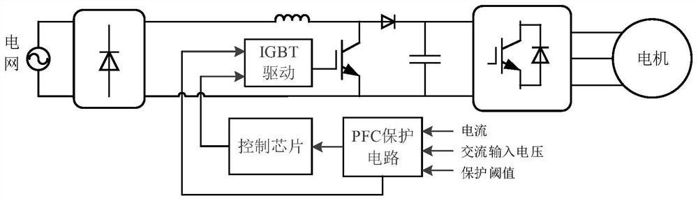
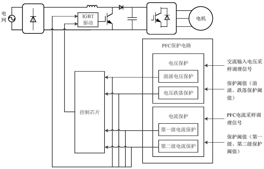
[0030] The present invention proposes a PFC circuit protection device, referring to Figure 1-Figure 4 , the PFC circuit includes a rectification circuit, the two input ends of the rectification circuit are connected to the two ends of the grid, and one output end of the rectification circuit is connected to one end of the diode through the inductor L1. The PFC circuit further includes an IGBT, the collector of the IGBT is connected between the inductor L1 and the diode, and the emitter of the IGBT is connected to the other output terminal of the rectification module. The PFC circuit also includes a capacitor, and the two ends of the capacitor are respectively connected with the other end o...


PUM


Abstract

The invention provides a PFC circuit protection device. The PFC circuit protection device can perform voltage protection and current protection simultaneously or successively. The current protection comprises first-stage current protection and second-stage current protection; and when a first-stage current protection threshold is smaller than or equal to a PFC current sampling conditioning signaland the PFC current sampling conditioning signal is smaller than a second-stage current protection threshold, the first-stage current protection is triggered, a PFC abnormal operation signal is output, an IGBT is immediately kept in a turn-off state, and after a control chip receives a corresponding signal, only the PWM output of the PFC is turned off while the whole machine is not controlled to be shut down; According to the voltage protection, an AC input voltage sampling conditioning signal is compared with a voltage protection threshold, and a PFC normal or abnormal operation signal is output according to a comparison result; and when the PFC abnormal operation signal is output, the IGBT is immediately kept in the turn-off state, and after the control chip receives the corresponding signal, only the PWM output is turned off while the whole machine is not controlled to be shut down. The invention also provides an air conditioner. According to the air conditioner, the abnormal current of the PFC can be effectively reduced, the IGBT can be quickly turned off, the damage to the IGBT is reduced, and unnecessary shutdown of the whole machine is avoided.

Description

technical field [0001] The invention belongs to the technical field of air conditioners, and in particular relates to a PFC circuit protection device and an air conditioner. Background technique [0002] In the application of air conditioners, the installation environment of the outdoor unit is complex, and problems such as surges and interference are prominent, resulting in abnormal voltage and current abnormalities in the PFC. Therefore, high requirements are placed on the reliability of the air conditioner controller. [0003] In response to the above problems, the method widely used in the industry is to add a PFC protection circuit to the controller, but the PFC protection device commonly used at present only includes the first-level current protection, which has the following defects: [0004] (1) There is only one level of current protection, and the user experience is difficult to guarantee. In the case of only the first-level current protection, in order to ensure ...

Claims


Application Information

Patent Timeline
Patent Type & Authority Applications(China)
IPC IPC(8): H02H3/08H02H3/20H02H3/06H02M1/42F24F11/88F24F11/89
CPCH02H3/08H02H3/20H02H3/066H02M1/4208F24F11/88F24F11/89Y02B70/10
Inventor 王乐三吴学全尹磊刘晓飞
Owner HISENSE (SHANDONG) AIR CONDITIONING CO LTD
Why Eureka
Try Eureka