
External grinding machining device for thin-wall non-metal part with inner ring groove and clamping method

A cylindrical grinding and processing device technology, applied in metal processing equipment, machine tools designed for grinding the rotating surface of workpieces, grinding/polishing equipment, etc. Unreasonable, difficult to guarantee the design size of parts, etc., to improve the clamping deformation method, prevent uneven grinding force, and improve the processing qualification rate

Active Publication Date: 2021-04-06
XIAN AERO ENGINE CONTROLS
View PDF10 Cites 1 Cited by
  • Summary
  • Abstract
  • Description
  • Claims
  • Application Information

AI Technical Summary

Problems solved by technology

The problems of this clamping method and processing device are as follows: 1) The material properties and structural characteristics of the parts are ignored. Since the material is easily deformed, the holes are positioned. Because the rigidity of the holes is relatively poor, and the parts have inner ring grooves, grinding The extrusion of the cutting force leads to low processing efficiency, large processing deformation, and uneven removal allowance; 2) The material selection and size of the gasket are unreasonable, the clamping force is not limited, and the hardness of the steel gasket is dozens of times higher than the parts In addition, the diameter of the gasket has a great influence on the clamping deformation of the part, the design size of the part is difficult to guarantee, and the processing pass rate is very low, which seriously affects the production cost and production schedule of the factory

Method used


Image

  • External grinding machining device for thin-wall non-metal part with inner ring groove and clamping method
  • External grinding machining device for thin-wall non-metal part with inner ring groove and clamping method
  • External grinding machining device for thin-wall non-metal part with inner ring groove and clamping method

Examples


Embodiment 1

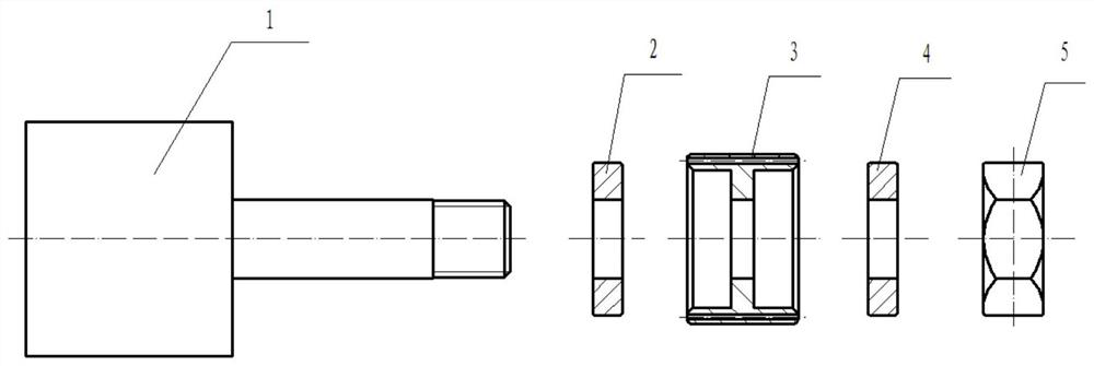
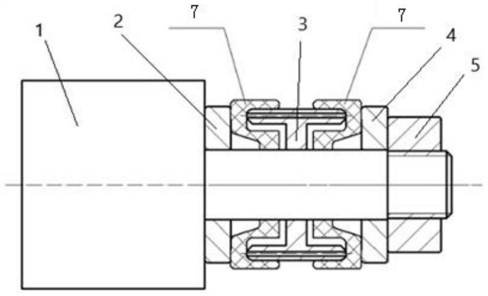
[0042] see figure 1 and figure 2 , in this embodiment, the mandrel 1 is a steel mandrel with threads and top holes, the mandrel 1 includes the middle polished rod part and the shoulders and threaded parts respectively located at both ends of the polished rod part, and the mandrel 1 shoulder carries out the shaft To the limit, the first gasket, the thin-walled non-metallic part 7 to be processed, the bushing 3 and the second gasket 4 are installed on the polished rod of the mandrel, and the threaded part is clamped with the nut 5. Tightness control.

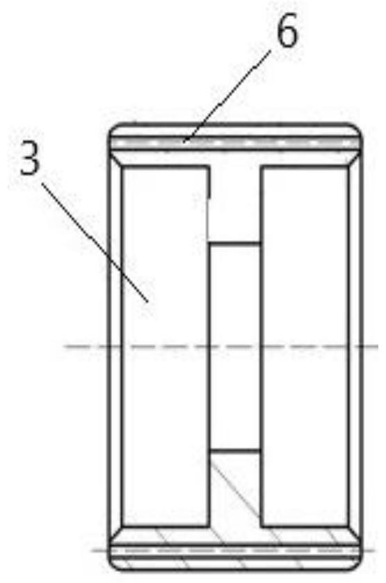
[0043] see image 3 , in this embodiment, the bushing 3 is a two-way concave bushing with vent holes. Extending inwardly, the longitudinal section of the bushing 3 is I-shaped.

[0044] In this embodiment, the outer circle of the bushing 3 matches the major diameter of the annular groove of the part, the diameter of the inner wall of the bushing 3 is at least 1mm smaller than the minor diameter of the inner ring groove of the...

Embodiment 2

[0063] like figure 2 As shown, the thin-walled non-metallic part 1 with an inner ring groove to be processed (the outer diameter of the part is Φ35.5mm, the major diameter of the inner ring groove is Φ30mm, the minor diameter of the inner ring groove is Φ21mm, the hole diameter is Φ13.5mm, and the material is rubber ) into one end of the two-way concave bushing, put part 2 into the other end of the bushing, the outer circle of the bushing matches the major diameter of the ring groove of the part, and the diameter of the inner wall of the bushing is smaller than the minor diameter of the inner ring groove of the thin-walled non-metallic part 7 to be processed At least 1mm, the bushing hole is matched with the mandrel, the depth from the end surface of the bushing to the bottom of the groove is at least 2mm greater than the depth of the annular groove of the part, to ensure that the bottom of the annular groove of the part and the end surface of the bushing 3 are tightly positio...


PUM

PropertyMeasurementUnit
thicknessaaaaaaaaaa

Abstract

The invention belongs to the field of machining, and relates to an external grinding machining device for a thin-wall non-metal part with an inner ring groove and a clamping method. The external grinding machining device comprises a mandrel, a bushing and a nut, wherein the bushing and the nut are sequentially arranged on the mandrel in a sleeving mode; the bushing is a bidirectional concave bushing and is of an annular cylinder structure, grooves are formed in the two end faces of the bushing, the longitudinal section of the bushing is in an I shape, and exhaust holes are formed in the bushing; and the external grinding machining device further comprises a first gasket and a second gasket which are arranged on the mandrel in a sleeving mode and arranged at the two ends of the bushing correspondingly, and the first gasket and the second gasket are the same in size and structure. According to the external grinding machining device for the thin-wall non-metal part with the inner ring groove and the clamping method, the specially-designed bidirectional concave bushing, the inner wall and the groove bottom of the inner ring groove of the part and the right end face of the part are positioned and clamped, and the mandrel is used for auxiliary positioning, so that the problems of uneven clamping stress and grinding deformation are solved, the qualification rate of the part is improved, and the stable and reliable quality is ensured.

Description

technical field [0001] The invention belongs to the field of mechanical processing, and relates to a cylindrical grinding and clamping method and processing device of a thin-walled non-metallic part with an inner ring groove. Background technique [0002] Cylindrical grinding of thin-walled non-metallic parts with inner ring grooves, due to the material is easily deformed during processing, the design dimensional tolerance is small, the processing deformation is serious, the qualified rate of parts processing is low, and the quality is difficult to guarantee, which affects the production progress. The current clamping method is to position and clamp the inner hole and end face of the part, and the processing device is composed of a mandrel, a steel gasket, and a nut. The problems of this clamping method and processing device are as follows: 1) The material properties and structural characteristics of the parts are ignored. Since the material is easily deformed, the holes are...

Claims


Application Information

Patent Timeline
Patent Type & Authority Applications(China)
IPC IPC(8): B24B5/35B24B5/50B24B1/00
CPCB24B5/35B24B5/50B24B1/00Y02P70/10
Inventor 张晶陶保平俞广胜范海波王发光程永朝翟婷婷刘娜
Owner XIAN AERO ENGINE CONTROLS
Learn More