Power output device of non-road diesel engine

A power output, diesel engine technology, applied in the direction of machines/engines, mechanical equipment, etc., can solve the problem that the power transmission mechanism cannot serve the agricultural engineering machinery market well, is easily involved in harvests, debris, industrial dust, and poor transmission stability and other problems, to achieve the effect of simple structure, ensuring stability and enhancing service life

Active Publication Date: 2017-08-11
GUANGXI YUCHAI MASCH CO LTD
View PDF7 Cites 2 Cited by
  • Summary
  • Abstract
  • Description
  • Claims
  • Application Information

AI Technical Summary

Problems solved by technology

At present, non-road mechanical transmission mechanisms are diverse and complex. Because of the extremely harsh operating environment, the existing power transmission mechanisms cannot serve the agricultural engineering machinery market well. The main disadvantages are as follows:
[0003] 1. The drive belt at the front end of the engine is easy to get involved in harvest, debris, industrial dust, etc., resulting in belt slippage, early wear, and breakage;
[0004] 2. The gear transmission mechanism of the transfer case, the two ends of the PTO output shaft are supported by rolling bearings, which has a complex structure, difficult disassembly and assembly, and high maintenance costs;
[0005] 3. The power output device with unilateral support gear has poor transmission stability, especially the helical gear transmission structure, and the thrust plate is subjected to unilateral axial force, which is prone to premature grinding and burning of tiles

Method used


Image

  • Power output device of non-road diesel engine
  • Power output device of non-road diesel engine
  • Power output device of non-road diesel engine

Examples


Embodiment Construction

[0028] The present invention will be further described below in conjunction with the specific embodiments in the accompanying drawings.

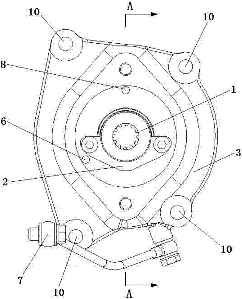
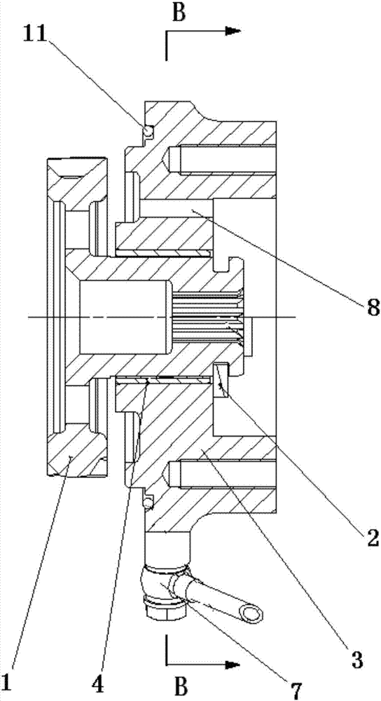
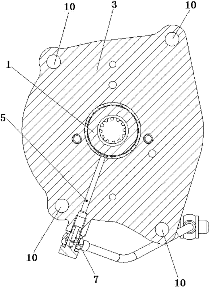
[0029] refer to Figure 1-5 , a power output device of a non-road diesel engine of the present invention includes a gear shaft 1 that can be connected with the rear gear train of the engine. The end of the shaft 1 far away from the gear train is provided with a thrust plate 2, which is used to prevent the gear shaft 1 from axially shifting, and the gear shaft 1 between the thrust plate 2 and the gear train is provided with a movable The shaft seat 3 connected with the engine gear chamber, the shaft seat 3 is used to support the gear shaft 1, and a bushing 4 is embedded between the gear shaft 1 and the shaft seat 3, and the bushing 4 is made of high wear-resistant material It is made to prevent the relative friction between the gear shaft 1 and the shaft seat 3 from being damaged; the shaft seat 3 is provided with an oil inlet passage 5 open...


PUM


Abstract

The invention discloses a power output device of a non-road diesel engine. The power output device comprises a gear shaft capable of being connected with a rear gear train of the engine. A thrust plate is arranged at the end, away from the gear train, of the gear shaft. The position, between the thrust plate and the gear train, of the gear shaft is sleeved with a shaft seat capable of being connected with an engine gear chamber. A bush is internally embedded between the gear shaft and the shaft seat. An oil inlet way which is arranged in the radial direction of the shaft seat and extends to the outer surface of the gear shaft is arranged on the shaft seat. Correspondingly, a high-position oil return hole which is formed in the axial direction of the shaft seat, extends to an inner cavity of the gear chamber and corresponds to the thrust plate in position is further formed in the shaft seat. The power output device is simple in structure; the thrust plate is arranged at the end, away from the gear train of the engine, of the gear shaft, and therefore the operating stability of the gear shaft is improved; meanwhile, the high-position oil return hole is additionally formed, and therefore lubricating and heat radiation of the thrust plate are enhanced; and the power output device is an independently-assembled integral device, demounting, mounting and maintaining are facilitated, and the maintaining cost is effectively reduced.

Description

technical field [0001] The invention relates to the technical field of engine manufacturing, more specifically, it relates to a power output device of a non-road diesel engine. Background technique [0002] In addition to the power output of the flywheel end of the crankshaft, non-road diesel engines also need power output from the pulley train and gear train. For example, the action of the harvesting mechanism of the harvester and silage machine in agricultural machinery needs to be driven by a hydraulic system, and the travel mechanism of the whole vehicle needs the front end The drive of the pulley system, the rotating mechanism of the transport tank in the construction machinery concrete mixer truck, the lifting mechanism of the bulldozer blade, etc. all need PTO to provide power. At present, non-road mechanical transmission mechanisms are diverse and complex. Because of the extremely harsh operating environment, the existing power transmission mechanisms cannot serve th...

Claims


Application Information

Patent Timeline
Patent Type & Authority Applications(China)
IPC IPC(8): F02B61/06
CPCF02B61/06
Inventor 秦江福杨淇竣叶珊刘振锋刘蓉
Owner GUANGXI YUCHAI MASCH CO LTD
Why Eureka
Try Eureka