Biochemical reaction tank sludge transfer system and sludge transfer method

A biochemical reaction and reaction tank technology, applied in chemical instruments and methods, water/sludge/sewage treatment, biological water/sewage treatment, etc., can solve problems such as damage to aeration pipes, low transfer efficiency, and damage to aerators. , to increase safety, reduce transport costs, and improve transport efficiency.

Pending Publication Date: 2021-04-06
JIANGSU SOPO CHEM +1
View PDF7 Cites 0 Cited by
  • Summary
  • Abstract
  • Description
  • Claims
  • Application Information

AI Technical Summary

Problems solved by technology

[0007] The technical problem to be solved by the present invention is: after the SBR reaction tank has been used for a long time, the aeration pipe is damaged, blocked, and the aerator is damaged. During maintenance, it is necessary to pump out the sludge in the reaction tank through a temporary submersible pump for maintenance and transfer. low efficiency

Method used


Image

  • Biochemical reaction tank sludge transfer system and sludge transfer method

Examples


Embodiment 1

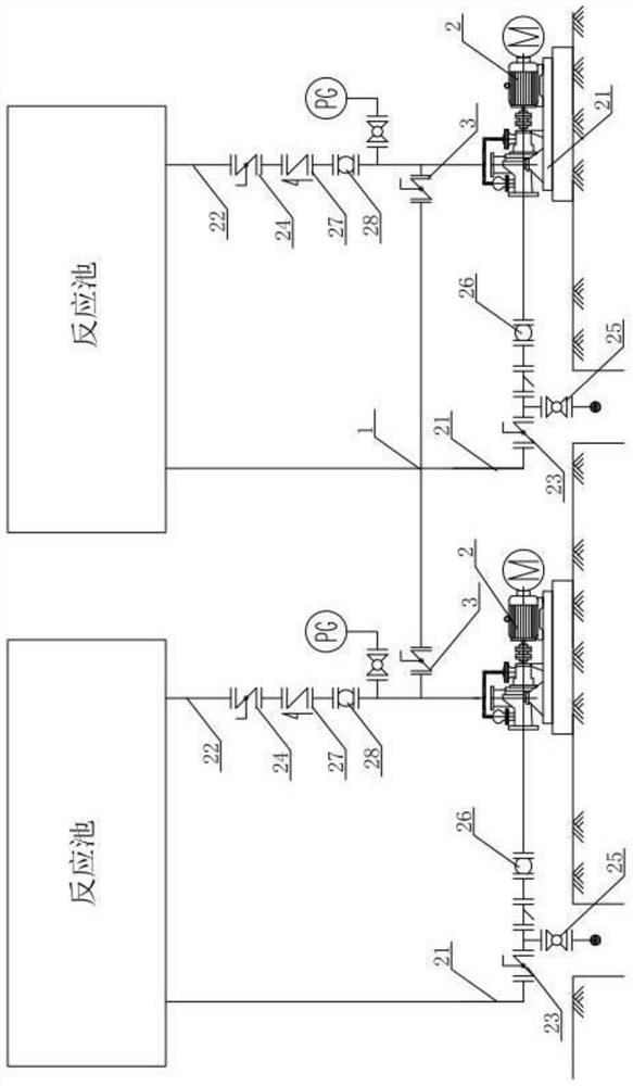
[0025]A biochemical reactive pool sludge transportation system, including at least two or more reaction tanks, and the outer side of each reaction cell is provided with a sewage circulation pump 2, the sewage circulation pump 2 is connected to the circular pump inlet line 21 and the circulating pump outlet pipe line 22, cycle A circulating pump inlet valve 23 is provided on the pump inlet line 21, and a circulating pump outlet valve 24 is provided on the circulating pump outlet line 22; a sludge transfer line 1 is connected between the circulating pump outlet pipe lines 22 of each reaction cell. The sludge transport line 1 achieves sludge transport between the reaction tanks between each other; the sludge transport valve 3 is provided at both ends of the sludge transfer line 1 and the position of the circular outlet pipeline 22 connected thereto. When the reactive pool sludge transport valve 3 is closed, two reaction tanks work independently. When these two sludge turn valves are tu...

Embodiment 2

[0033]A biochemical reaction pool sludge transfer method, including the following steps,

[0034](1) After one of the biochemical reactive pool sludge precipitation, first eliminate the upper cleaner by decanter, open its corresponding sludge transfer valve and sludge transport line, the other end of the sludge needs to transport the sludge transfer in the end of the reaction pool end. Mud turnover;

[0035](2) Close the circulation pump outlet valve of the reaction cell to be transferred to the sludge, keep the sewage circulation pump continuously, and the sludge in the reaction pool is transferred to the corresponding reaction cells of the sludge transport line communication.

[0036](3) The end of the transfer, the reaction tank to be transported to the sludge is evacuated.

[0037]Similarly, the sludge in other reaction cells can also be transported into the reaction tank connected thereto.

[0038]Under normal operation, close the sludge transport valve 3 between the reaction pool, each react...


PUM


Abstract

The invention relates to the technical field of sewage treatment, in particular to a biochemical reaction tank sludge transfer system and a sludge transfer method. The biochemical reaction tank sludge transfer system comprises at least two reaction tanks, a sewage circulating pump is correspondingly arranged on the outer side of each reaction tank and connected with a circulating pump inlet pipeline and a circulating pump outlet pipeline, a circulating pump inlet valve is arranged on each circulating pump inlet pipeline, and a circulating pump outlet valve is arranged on each circulating pump outlet pipeline. A sludge transfer pipeline is connected between circulating pump outlet pipelines of the reaction tanks; and sludge transfer valves are arranged at the two ends of the sludge transfer pipelines and the circulating pump outlet pipelines connected with the sludge transfer pipelines. Sludge transfer is achieved through self circulating pump pipeline connection, a temporary submersible pump is not needed, the transfer efficiency is greatly improved, meanwhile, the transfer safety is improved, and meanwhile the transfer cost is greatly reduced.

Description

Technical field[0001]The present invention relates to the field of sewage treatment, in particular to a biochemical reaction pool sludge transportation system and a sludge transport method.Background technique[0002]The order-batch active sludge method (SBR) is an operational activated sludge treatment process by intermittent aeration. The process will change the conventional aeration cell, the distribution of the sedimentation tank from the space. Distributed, integrated simple structures, has a small area, easy to settle, and can achieve synchronous denitrification and phosphorus, intermittent aeration mainly by circulating pump, sewage circulation pipe, aerator, aeration fan, The intake pipeline consists of a liquid pumped through the circulating pump to the aeration via a sewage circulation pipe, and the air transported by the aeration fan via the intake pipeline, forming an oxygen-rich gas-liquid mixture, in the biochemical reaction tank (refer to SBR A strong mixing is produced...

Claims


Application Information

Patent Timeline
Patent Type & Authority Applications(China)
IPC IPC(8): C02F3/12
CPCC02F3/1263C02F2203/006C02F2301/046C02F2209/03C02F2303/14Y02W10/10
Inventor 朱桂生张远鹏胡宗贵代松涛盛英俊马克和华良唐丽叶兴平
Owner JIANGSU SOPO CHEM
Why Eureka
Try Eureka