High-precision high-strength carbon fiber thin-wall pipe end face connecting structure

A technology of high-strength carbon fiber and thin-walled pipes, which is applied in the direction of connecting components, rod connections, mechanical equipment, etc., and can solve problems such as poor aesthetics, inability to cut pipes precisely, and poor strength

Pending Publication Date: 2021-04-06
巨硕精密机械(常熟)有限公司
View PDF0 Cites 0 Cited by
  • Summary
  • Abstract
  • Description
  • Claims
  • Application Information

AI Technical Summary

Problems solved by technology

[0005] 1) The installation process is complicated and the work intensity is high;
[0006] 2) The assembly accuracy is poor, the pipe cannot be cut precisely, and the accuracy cannot be guaranteed during the winding process;
[0007] 3) Dressing and

Method used


Image

  • High-precision high-strength carbon fiber thin-wall pipe end face connecting structure
  • High-precision high-strength carbon fiber thin-wall pipe end face connecting structure
  • High-precision high-strength carbon fiber thin-wall pipe end face connecting structure

Examples


Embodiment 1

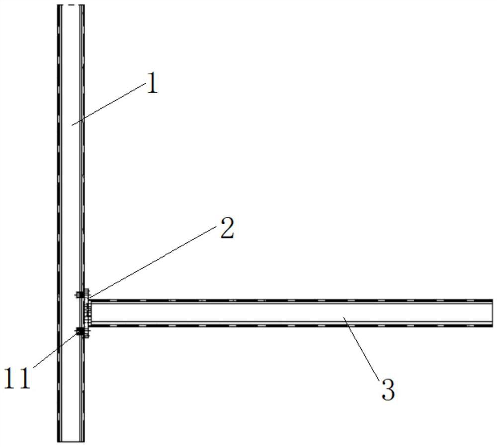
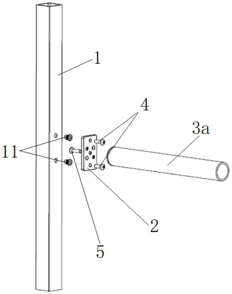
[0032] Such as figure 1 , figure 2 and Figure 4 As shown, a high-precision, high-strength carbon fiber thin-walled pipe end surface connection structure of the present invention includes a square tube 1, a connecting piece 2 fixed to the side wall of the square tube 1, and a connecting piece 2 fixed to the side of the square tube 1. Connecting pipe 3, square pipe 1 is provided with at least two rivet nuts 11; connecting piece 2 is provided with fixed taper hole (here is central fixed taper hole 22a), connecting pipe (here is circular connecting pipe 3a) The end facing the connecting piece 2 has an end surface (not marked), and the connecting piece 2 is fixed to the end surface by a number of reverse screws 5 embedded in the central fixing taper hole 22a; the connecting piece 2 is provided with a matching blind rivet nut on the side facing the square tube 1 11, the connecting piece 2 is fixed on the blind rivet nut 11 through the forward screw 4 passing through the counterb...

Embodiment 2

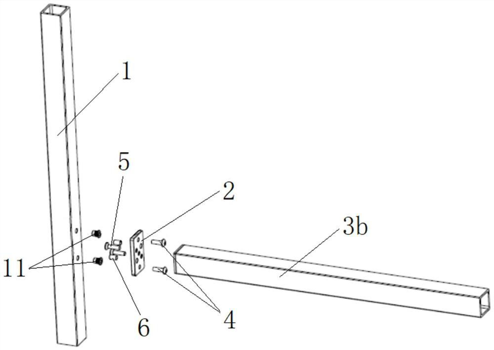
[0036] Such as figure 1 , image 3 and Figure 4 As shown, the difference from Example 1 is that the connecting pipe is a square connecting pipe 22b, the connecting piece 2 has two diagonal fixing taper holes 22b, and the reverse screw 4 passes through the diagonal fixing taper holes 22b to connect with the square The end face of the tube 3b is fixed. When the connecting pipe is a square connecting pipe 22b, its relative position to the connecting piece 2 is determined by the diagonal line, which can prevent the position accuracy deviation caused by the angle.

[0037] Such as image 3 and Figure 4 As shown, the connecting piece 2 is also provided with a diagonal pin hole 23, and the diagonal line where the diagonal pin hole 23 is located is perpendicular to the diagonal line where the diagonally fixed taper hole 22b is located. Corresponding to the pin hole (not exposed) of the corner pin hole 23 , the diagonal pin hole 23 and the pin hole are butted through the fixing ...


PUM


Abstract

The invention belongs to the technical field of positioning supports, and relates to a high-precision high-strength carbon fiber thin-wall pipe end face connecting structure. The connecting structure comprises a square pipe, a connecting piece fixed to the side wall of the square pipe and a connecting pipe fixed to the side of the square pipe through the connecting piece, and at least two rivet nuts are arranged on the square pipe. The connecting piece is provided with a fixing taper hole, the end, facing the connecting piece, of the connecting pipe is provided with an end face, and the connecting piece is fixed to the end face through a plurality of reverse screws embedded into the fixing taper hole. Counter bores matched with the rivet nuts are formed in the faces, facing the square pipe, of the connecting piece, and the connecting piece is fixed to the rivet nuts through forward screws penetrating through the counter bores. According to the connecting structure, the strength reduction of a punched carbon fiber thin-walled pipe is compensated through the rivet nuts, and the connecting piece is used for connecting, positioning and fixing, so that the connecting pipe can be accurately and firmly fixed on the side of the square pipe.

Description

technical field [0001] The invention relates to the technical field of positioning brackets, in particular to a high-precision and high-strength carbon fiber thin-wall pipe end face connection structure. Background technique [0002] The machinery manufacturing industry is the cornerstone of modern industry. Nowadays, it has been focusing on improving productivity and processing quality for a long time. With the enhancement of environmental protection awareness and the increasing shortage of natural resources, the limited use of energy and resources in the production process and the reduction of pollution in production play an increasingly important role. Facing the dual challenges of environment and energy, the transformation of the manufacturing industry has also brought new development opportunities for the industry. With the revolutionary breakthrough and cross integration of information technology, new energy, new materials and other important fields and frontier direc...

Claims


Application Information

Patent Timeline
IPC IPC(8): F16B7/18F16B7/20
CPCF16B7/18F16B7/20
Inventor 褚春旭叶超
Owner 巨硕精密机械(常熟)有限公司
Why Eureka
Try Eureka