Automatic liquid oxygen filling equipment

A liquid oxygen and equipment technology, applied in the field of liquid oxygen automatic perfusion equipment, can solve the problems of low production cost of liquid oxygen, the pressure of liquid oxygen storage tank is prone to danger, etc., and achieves the effects of convenient and fast process, convenient operation and simple equipment structure.

Inactive Publication Date: 2021-04-06
宿迁宇尔恒电子商务有限公司
View PDF0 Cites 0 Cited by
  • Summary
  • Abstract
  • Description
  • Claims
  • Application Information

AI Technical Summary

Problems solved by technology

[0002] In the industrial gas industry, the production cost of producing liquid oxygen by cryogenically separating air is low, so the tail gas in the liquid oxygen packaging process is generally emptied and discarded. In the prior art, liquid oxygen filling is implemented by using pressure difference. That is, the liquid pipeline of the liquid oxygen storage tank is connected with the liquid pipeline of the cryogenic insulating gas cylinder, and the gas venting pipeline of the cryogenic insulating gas cylinder is opened so that the pressure of the gas cylinder is lower than the pressure of the liquid oxygen storage tank, and the liquid oxygen flows into the cryogenic insulating gas cylinder, and the liquid The pressure of the oxygen storage tank is too high, which is very easy to cause danger. Since most of the liquid oxygen perfusion in today's technology requires manual operation, an automatic liquid oxygen perfusion equipment that can automatically adjust the pressure is needed.

Method used


Image

  • Automatic liquid oxygen filling equipment
  • Automatic liquid oxygen filling equipment
  • Automatic liquid oxygen filling equipment

Examples


Embodiment Construction

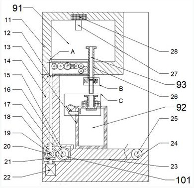
[0016] Combine below Figure 1-4 The present invention is described in detail, wherein for the convenience of description, the orientations mentioned below are now specified as follows: figure 1 The projection relationship of itself is the same as the up, down, left, right, front, and rear directions.

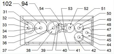
[0017] combined with Figure 1-4 The liquid oxygen automatic perfusion equipment includes a body 11 and a base 14 fixedly connected to the bottom end of the body 11. A liquid oxygen chamber 91 is arranged in the body 11, and the liquid oxygen chamber 91 Liquid oxygen is stored, a liquid oxygen storage tank 13 is arranged above the base 14, a storage cavity 92 is arranged in the liquid oxygen storage tank 13, and the bottom end of the liquid oxygen cavity 91 is slidable up and down in the body 11. A perfusion gun 26 is provided, a perfusion cavity 93 is provided inside the perfusion gun 26, a transmission cavity 94 is provided in the fuselage 11 on the left side of the perfusi...


PUM


Abstract

The invention discloses automatic liquid oxygen filling equipment. The automatic liquid oxygen filling equipment comprises a machine body and a base fixedly connected to the bottom end of the machine body. A liquid oxygen cavity is formed in the machine body. Liquid oxygen is stored in the liquid oxygen cavity. A liquid oxygen storage tank is arranged above the base. A storage cavity is formed in the liquid oxygen storage tank. A filling gun is arranged at the position, at the bottom end of the liquid oxygen cavity, in the machine body in an up-down sliding manner. A filling cavity is formed in the filling gun. A transmission cavity is formed in the position, on the left side of the filling gun, in the machine body. A filling nozzle is arranged at the top end of the liquid oxygen storage tank in an up-down sliding manner. An oxygen inlet cavity is formed in the filling nozzle. The automatic liquid oxygen filling equipment is simple in structure and convenient to operate, automatic liquid oxygen filling can be achieved, all procedures are matched without influences, the pressure in the storage tank can be automatically adjusted according to the measured pressure value in the liquid oxygen filling process, the process is convenient and fast, waste of manpower and material resources is effectively avoided, and therefore cost is greatly reduced.

Description

technical field [0001] The invention relates to the related field of liquid oxygen storage tanks, in particular to a liquid oxygen automatic perfusion device. Background technique [0002] In the industrial gas industry, the production cost of liquid oxygen by cryogenic separation of air is relatively low, so the tail gas of liquid oxygen in the sub-packaging process is generally emptied and abandoned. That is, the liquid pipeline of the liquid oxygen storage tank is connected with the liquid pipeline of the low temperature thermal insulation gas cylinder, and the gas venting pipeline of the low temperature thermal insulation gas cylinder is opened so that the pressure of the gas cylinder is lower than the pressure of the liquid oxygen storage tank, and the liquid oxygen flows into the low temperature thermal insulation gas cylinder. Excessive pressure in the oxygen storage tank is very prone to danger. Since most of the current technology liquid oxygen perfusion requires ma...

Claims


Application Information

Patent Timeline
Patent Type & Authority Applications(China)
IPC IPC(8): F17C1/00F17C5/02F17C13/02F17C13/04
CPCF17C1/00F17C5/007F17C13/025F17C13/04F17C2205/0323F17C2221/011F17C2223/013F17C2227/01F17C2250/043
Inventor 申正芹
Owner 宿迁宇尔恒电子商务有限公司
Why Eureka
Try Eureka