
Method and device for capturing sintering machine tail section picture

A section and picture technology, applied in the field of image recognition, can solve the problem of loss of sintering information

Active Publication Date: 2021-04-06
BEIJING SHOUGANG AUTOMATION INFORMATION TECH
View PDF3 Cites 2 Cited by
  • Summary
  • Abstract
  • Description
  • Claims
  • Application Information

AI Technical Summary

Problems solved by technology

However, in the actual production process, the sintering machine is constantly moving, and images need to be acquired continuously. If the extracted images are not typical or the images themselves are not complete, the sintering information will be lost.

Method used


Image

  • Method and device for capturing sintering machine tail section picture
  • Method and device for capturing sintering machine tail section picture
  • Method and device for capturing sintering machine tail section picture

Examples


Embodiment 1

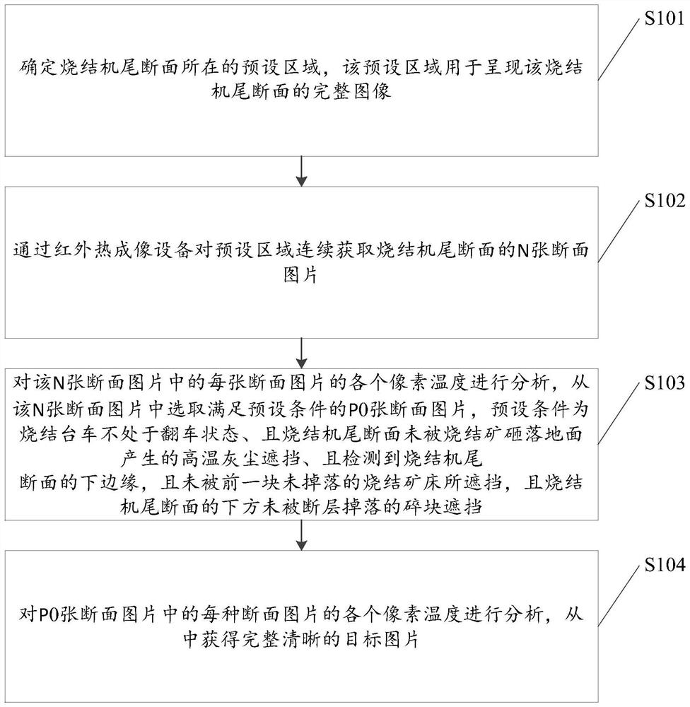
[0062] Embodiment 1 of the present invention provides a method for capturing a section picture of a sintering machine tail, such as figure 1 shown, including:

[0063] S101. Determine a preset area where a sintering machine tail section is located, and the preset area is used to present a complete image of the sintering machine tail section.

[0064] S102. Continuously acquire N cross-sectional pictures of the tail section of the sintering machine in a preset area by using an infrared thermal imaging device.

[0065] S103, analyze the temperature of each pixel in each of the N cross-sectional pictures, select P0 cross-sectional pictures from the N cross-sectional pictures that meet the preset condition, and the preset condition is that the sintering trolley is not in an overturned state , and the section of the tail of the sintering machine is not blocked by the high-temperature dust generated by the sinter falling on the ground, and the lower edge of the section of the tail ...

Embodiment 2

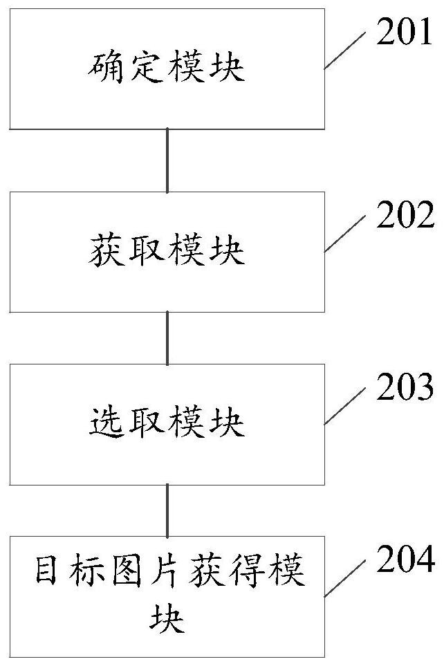
[0122] Based on the same inventive concept, Embodiment 2 of the present invention also provides a device for capturing pictures of sintering machine tail sections, such as figure 2 shown, including:

[0123] A determining module 201, configured to determine a preset area where the tail section of the sintering machine is located, and the preset area is used to present a complete image of the tail section of the sintering machine;

[0124] An acquisition module 202, configured to continuously acquire N cross-sectional pictures of the tail section of the sintering machine in the preset area through an infrared thermal imaging device;

[0125] The selection module 203 is configured to analyze the temperature of each pixel in each of the N cross-sectional pictures, and select P0 cross-sectional pictures from the N cross-sectional pictures that meet the preset conditions, and the preset conditions The sintering trolley is not in the overturned state, and the tail section of the s...

Embodiment 3

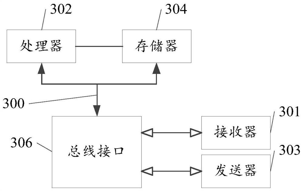
[0146] Based on the same inventive concept, Embodiment 3 of the present invention provides an electronic device, such as image 3 As shown, it includes a memory 304, a processor 302, and a computer program stored on the memory 304 and operable on the processor 302. When the processor 302 executes the program, the above steps of the method for capturing the sintering machine tail section picture are realized. .

[0147] Among them, in image 3 In, bus architecture (represented by bus 300), bus 300 may include any number of interconnected buses and bridges, bus 300 will include one or more processors represented by processor 302 and various types of memory represented by memory 304 circuits linked together. The bus 300 may also link together various other circuits, such as peripherals, voltage regulators, and power management circuits, etc., which are well known in the art and thus will not be further described herein. The bus interface 306 provides an interface between the b...


PUM


Abstract

The invention relates to the technical field of image recognition, in particular to a method and a device for capturing a sintering machine tail section picture, and the method comprises the steps: determining a preset region where a sintering machine tail section is located; continuously obtained n section pictures of the sintering machine tail section from the preset area through infrared thermal imaging equipment; analyzing each pixel temperature of each section picture, selecting P0 section pictures meeting a preset condition from the N section pictures, the preset condition being that the sintering trolley is not in a turnover state and the sintering machine tail section is not shielded by high-temperature dust generated when the sintering machine tail section is hit by sinter to fall to the ground, and detecting the lower edge of the sintering machine tail section, wherein the section is not shielded by the previous sinter bed which does not fall off, and the lower part of the section is not shielded by fragments falling off from the fault; the temperature of each pixel of each section picture in the P0 section pictures is analyzed to obtain the target picture, and the information of the sintering quality is obtained according to the clear and complete picture, so that the guidance is provided for the operation of the sintering process.

Description

technical field [0001] The invention relates to the technical field of image recognition, in particular to a method and device for capturing a section picture of a tail of a sintering machine. Background technique [0002] The picture of the bed layer section at the end of the sintering machine contains a lot of sintering quality information, and, using machine vision and image processing technology, this information can be obtained to provide guidance for the operation of the sintering process. However, in the actual production process, the sintering machine is constantly moving, and images need to be acquired continuously. If the extracted images are not typical or the images themselves are not complete, the sintering information will be lost. [0003] Therefore, how to obtain a complete and clear picture of the best section of the sinter tail is a technical problem to be solved urgently. Contents of the invention [0004] In view of the above problems, the present inve...

Claims


Application Information

Patent Timeline
IPC IPC(8): G01N25/00G06T7/00
CPCG01N25/00G06T7/0002G06T2207/10048
Inventor 胡振超秦雪刚李昭蓉杨伟强李亮举邱成国
Owner BEIJING SHOUGANG AUTOMATION INFORMATION TECH
Learn More