
Lens MTF distortion correction method and device

A distortion correction and distortion correction technology, applied in image data processing, instruments, calculations, etc., can solve problems such as insufficient objectivity, inability to real-time dynamic compensation, and inability to truly reflect the actual situation of the lens to be tested, and achieve the effect of improving measurement accuracy.

Inactive Publication Date: 2021-04-06
广东省傲来科技有限公司
View PDF1 Cites 2 Cited by
  • Summary
  • Abstract
  • Description
  • Claims
  • Application Information

AI Technical Summary

Problems solved by technology

The problems that exist in this way are: first, real-time dynamic compensation is not possible; second, distortion compensation based on a single individual test distortion as a whole cannot truly reflect the actual situation of each lens to be tested
[0004] Although the existing technology realizes dynamic compensation, the compensation scheme is to calculate the proportional relationship between the off-axis field of view after distortion and the central field of view, so as to correct the selected frequency parameters when extracting the specific MTF from the spatial frequency curve
The problem with this is that the method of correcting the frequency is not objective enough. For example, when the lens is tilted, the proportional relationship between the off-axis / peripheral field of view and the central field of view cannot truly reflect the distortion characteristics of the product itself.

Method used


Image

  • Lens MTF distortion correction method and device
  • Lens MTF distortion correction method and device
  • Lens MTF distortion correction method and device

Examples


Embodiment Construction

[0030]Next, the technical solutions in the embodiments of the present invention will be apparent from the embodiment of the present invention, and it is clearly described, and it is understood that the described embodiments are merely embodiments of the present invention, not all of the embodiments. Based on the embodiments of the present invention, there are all other embodiments obtained without making creative labor without making creative labor premises.

[0031]The present invention provides a method of lens MTF distortion correction, including the following steps:

[0032]Step 1: Follow the test points on the image, calculate the distortion correction parameters, and there are 48 points on the Reticle. The design coordinates are (x11, y11), (x12, y12), ..., (x48, y48), in actual The pixel coordinate of the reference point is obtained (IX11, IY 11), (IX48, IY48), respectively, for radial distortion and tangential distortion, respectively, in consideration of radial distortion and tan...


PUM


Abstract

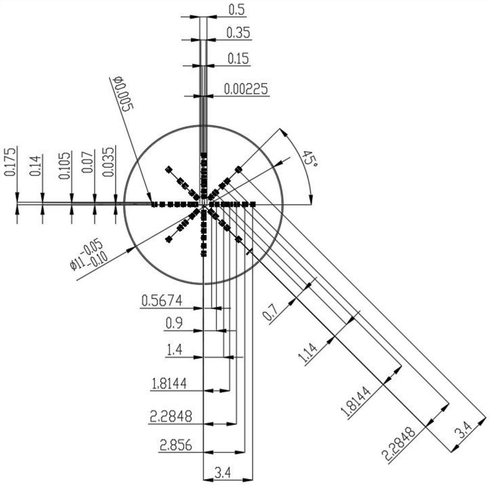
The invention discloses a lens MTF distortion correction method, and relates to the field of lens correction, and the method comprises five steps: firstly following a test point on an image, calculating a distortion correction parameter, then obtaining a distortion correction image, extracting AOI (Area of interest), calculating LSF (Line spread function), carrying out fast Fourier transform, and obtaining an MTF curve. The invention also discloses a lens MTF distortion correction device, which comprises a to-be-tested lens, the to-be-tested lens is a semitransparent chromium layer, one side of the to-be-tested lens is coated with a soda glass coating, the middle part of the to-be-tested lens is provided with a cross slit, and the cross slit is provided with a plurality of linearly distributed test patterns. According to the invention, dynamic distortion compensation correction can be carried out on each specific lens in the lens MTF measurement process, so that the measurement precision can be improved.

Description

Technical field[0001]The present invention relates to the field of lens correction, and more particularly to a method and apparatus for lens MTF distortion correction.Background technique[0002]Existing technologies and products, are not perfect for the distortion correction and compensation of the lens, and some programs cannot be dynamically corrected, and some planned corrections are not ideal.[0003]In the prior art, if distortion correction is required, it is necessary to use one correction distortion Reticle to perform distortion measurement, and then correct the distortion compensation coefficient of this test when actually produced. The problem is: First, it cannot be dynamically compensated in real time; second, with a single individual test distortion as a whole distortion compensation, the actual situation of each to be tested is not true.[0004]Although the prior art has realized dynamic compensation, its compensation scheme is to calculate the proportional relationship bet...

Claims


Application Information

Patent Timeline
IPC IPC(8): G06T5/00G06T5/10
CPCG06T5/10G06T2207/20056G06T5/80
Inventor 张自然黎艺文蒋煜麦明秀杨智尹尚军
Owner 广东省傲来科技有限公司
Learn More