
Transformer valve sleeve insulation support and installation guide structure assembly and assembly method

A technology of insulating support and guiding structure, applied in the direction of transformer/inductor coil/winding/connection, inductance/transformer/magnet manufacturing, electrical components, etc., it can solve the problem that it is not easy to form a reliable support structure and the installation structure of the valve casing is stable Poor performance, inconvenient orientation of the valve casing, etc., to reduce the mechanical stress of the box wall, reduce the risk of oil leakage, and have good practicality

Active Publication Date: 2021-04-06
SHANDONG POWER EQUIP +1
View PDF12 Cites 2 Cited by
  • Summary
  • Abstract
  • Description
  • Claims
  • Application Information

AI Technical Summary

Problems solved by technology

[0003] The installation structure of this kind of valve sleeve has poor stability, and it is not easy to form a reliable support structure; and it is inconvenient to guide the valve sleeve during on-site installation. If the operation is not done properly, the tail of the valve sleeve may be tilted, thereby damaging the outgoing line in the valve lifting seat Device and CT (current transformer on transformer valve bushing)

Method used


Image

  • Transformer valve sleeve insulation support and installation guide structure assembly and assembly method
  • Transformer valve sleeve insulation support and installation guide structure assembly and assembly method
  • Transformer valve sleeve insulation support and installation guide structure assembly and assembly method

Examples


Embodiment Construction

[0026] The technical solutions of the present invention will be clearly and completely described below in conjunction with the accompanying drawings. Apparently, the described embodiments are part of the embodiments of the present invention, not all of them.

[0027] A transformer valve bushing insulation support and installation guide structure assembly, comprising: a valve bushing insulation support structure, and a valve bushing installation guide structure.

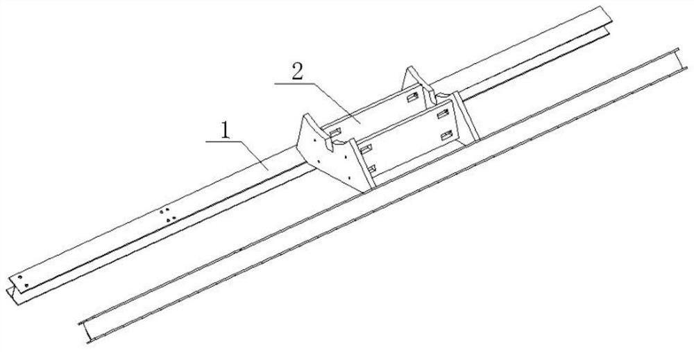
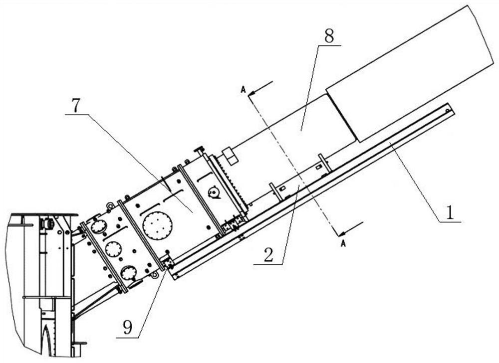
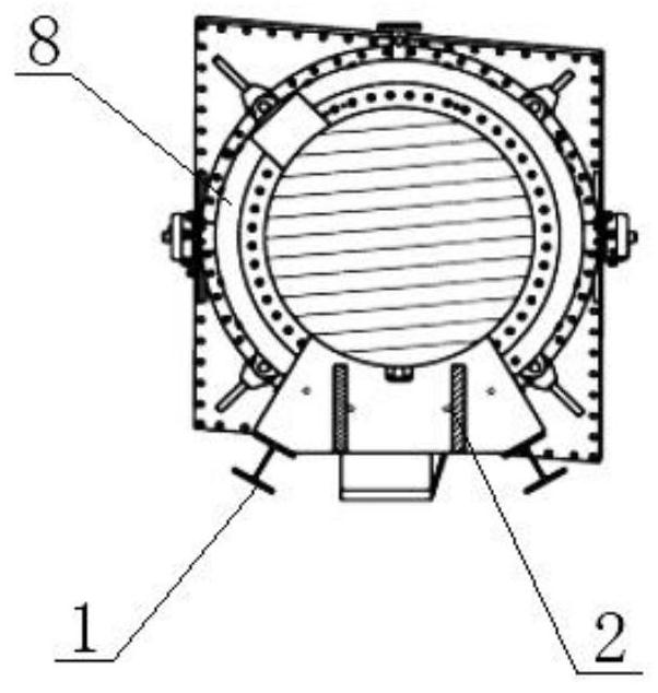
[0028] Such as figure 1 As shown, it is a schematic diagram of the installation guide structure of the embodiment of the present invention; as figure 2 As shown, it is a schematic diagram of the use state of the installation guide structure of the embodiment of the present invention; as image 3 As shown, it is a cross-sectional view of the installation guide structure of the embodiment of the present invention along the direction A. The valve sleeve 8 is fixedly installed on the valve lifting seat 7, and two detac...


PUM

PropertyMeasurementUnit
thicknessaaaaaaaaaa
thicknessaaaaaaaaaa

Abstract

The invention relates to a transformer valve sleeve insulation support and installation guide structure assembly. The transformer valve sleeve insulation support and installation guide structure assembly comprises an installation guide structure used for installing a valve sleeve on a valve lifting base and an insulation supporting structure used for supporting the valve sleeve. The installation guide structure comprises two detachable guide rods fixedly arranged on the valve lifting base and guide cushion blocks movably arranged on the guide rods. The insulation supporting structure is a frame type insulation supporting structure mainly made of I-shaped steel and comprises a supporting structure and a glass fiber insulation structure. The invention further relates to an assembly method of the transformer valve sleeve insulation support and installation guide structure assembly. By means of the tool design of the installation guide structure, inclination of the tail of the valve sleeve caused by hoisting errors and other operations during installation is avoided, structural reinforcement can be conducted on existing transformer valve sleeve installation, the connecting rigidity of the valve lifting base and an oil tank is improved, the structural principle is simple, practicability is good, and long-term safe operation of the structure is guaranteed. And the purpose of popularization and application on the + / -800kV converter transformer is achieved.

Description

technical field [0001] The invention belongs to the field of manufacturing high-voltage large-scale converter transformers, and in particular relates to a structural component and an assembly method that require reinforced insulation support and installation guidance for transformer valve bushings. Background technique [0002] The valve side voltage level of the ±800kV converter transformer is high. The valve bushing is generally arranged on the side wall of the short axis of the oil tank. The valve bushing is installed and fixed on the valve riser seat to ensure the insulation distance between the live part of the valve bushing and other places. And the two valve sleeves are approximately arranged in a V shape with respect to the central plane of the major axis. [0003] The installation structure of this kind of valve sleeve has poor stability and it is not easy to form a reliable support structure; and it is inconvenient to guide the valve sleeve during on-site installat...

Claims


Application Information

Patent Timeline
Patent Type & Authority Applications(China)
IPC IPC(8): H01F27/32H01F41/00
CPCH01F27/32H01F41/00
Inventor 张曼玉马玎郭鹏鸿王明胜杨仁毅贾志玲周斌柴东新杨伟光张阳阳甄浩宇邵会朋王栋栋
Owner SHANDONG POWER EQUIP
Learn More